
NAVAIR 01-1A-505-2
009 02
TO 00-25-255-1
Page 3
TM 1-1500-323-24-2
16. Coupling Type. The coupling type denotes bayonet
or threaded coupling.
17. Insert Configuration. The insert configuration is
the insert arrangement by number and size of contacts
used.
18. Contact Style. The contact style is a letter denoting
type of contact.
19. Alternate Polarizing Position. The alternate
positions indicate insert polarization other than the
normal position.
20. DESIGN AND CONSTRUCTION. Connectors and
accessories are designed and constructed to withstand
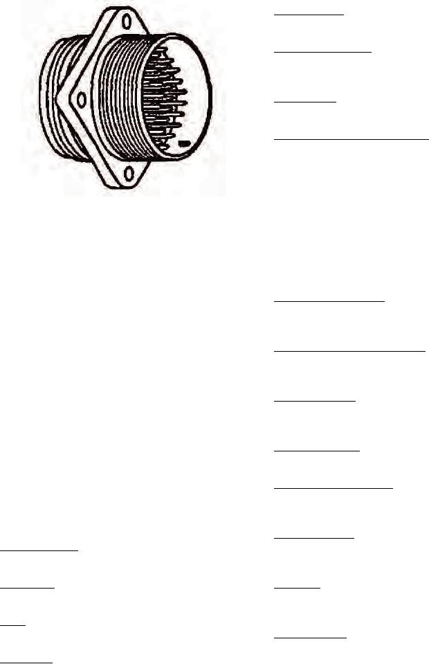
Figure 1. MIL-DTL-26500 Typical Connector
normal handling incidental to maintenance and
installation (Figure 3).
7. MATING SEAL. Plugs and receptacles with pin
21. INSERTS. The entire insert of the connector
inserts have a resilient face with individual pin barriers
assembly is essentially one integral part designed to
to seal against the hard face socket insert. The resilient
provide suitable support and sealing around contacts.
interface seal provides individual contact seal in mated
condition between each contact and shell.
22. Crimp Snap-In Contacts. Snap-in contacts designed
to AS39029 can be crimped with standard M22520/1
8. SHELL. Shells including mounting flanges are of
crimp tool.
one-piece construction and designed to retain their
inserts in one position by mechanical means.
23. Closed-Entry Socket Contacts. These contacts
eliminate damage from abuse by test probes and help
9. COUPLING. Connectors shall be capable of being
to correct any misaligned pins during engagement.
fully coupled and uncoupled without use of tools.
24. Contact Insertion. Insertion is accomplished from
10. POLARIZATION. Connectors are polarized as
rear of connector. When contact is fully inserted, the
denoted by their part numbers. This means that the
clip tines snap securely behind contact shoulder.
master keyway is rotated to prevent mis-mating of
similar connectors in a similar location. A plug with a
25. Contact Extraction. Extraction is accomplished with
given polarization letter will mate with a receptacle
a front-inserted extraction tool.
with same letter. The inserts do not rotate, only the
keyway is rotated.
26. Contact Retaining Clip. The retaining clip is
completely encased in a tough plastic wafer to protect
11. PART NUMBER. The following paragraphs contain
clip from damage.
information necessary for proper selection and
procurement of connector (Figure 2).
27. Moisture Sealing. A complete seal is achieved by
12. Military Prefix. The prefix denotes military
combining four seals; shell, peripheral, interfacial,
standard.
and wire seals.
13. Shell Style. The shell style denotes type and
28. Shell Seal. Shell seal is effected when plug shell
mounting of the connector.
pushes against sealing ring in receptacle when
connectors are mated.
14. Class. The class indicates the environment resisting
abilities.
29. Peripheral Seal. A peripheral seal is around the
edge of pin insulator and designed so that when
15. Shell Size. The shell size is indicated by a
mating the connector, tension is put on seal and greatly
progressive numbering system.
reduces compression set.

