
NAVAIR 01-1A-505-2
011 02
TO 00-25-255-1
Page 9
TM 1-1500-323-24-2
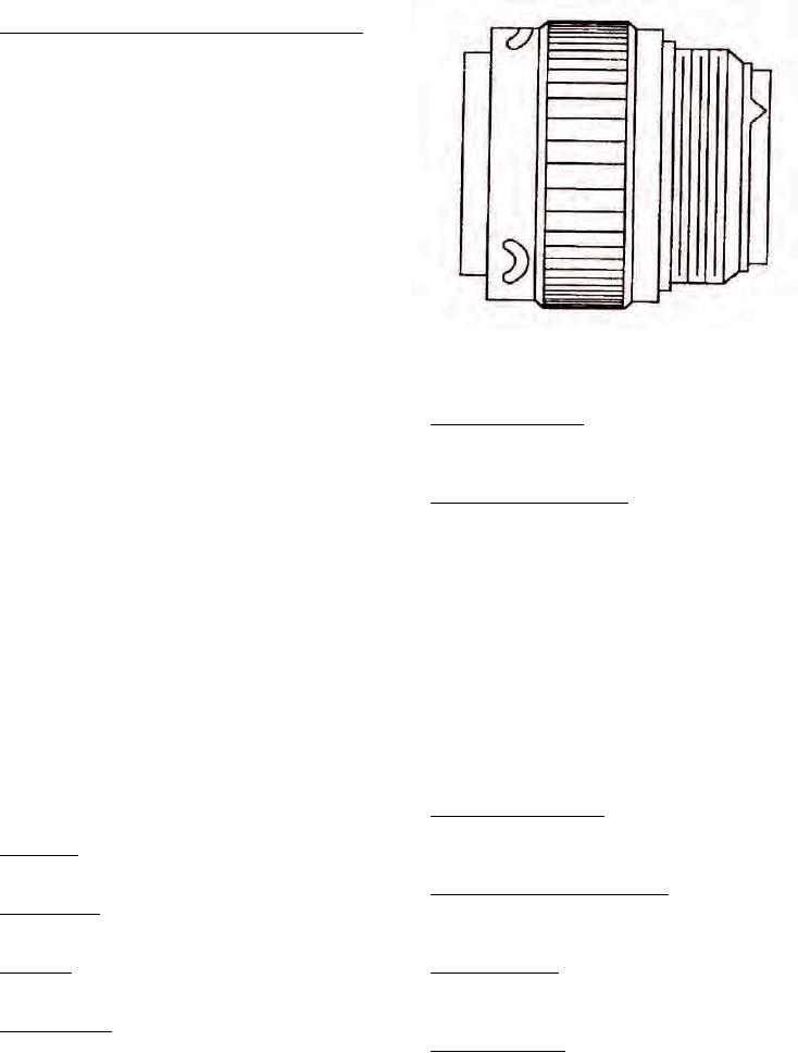
46. NAS1599 BAYONET COUPLED CONNECTORS.
47. Bayonet coupled type connectors NAS1599 conform
to MIL-C-26482 insert configurations with crimp rear
release contacts (Figure 6).
48. GROMMET SEALING PLUGS. The grommets of
environment resisting connectors are designed to accept
sealing plugs in accordance with NAS1599 to be used
where unwired contacts are placed. The connector
when ordered as a unit will have sealing plugs enclosed
to equal 15 percent of the number of contacts but not
less than one.
49. MATING SEAL. Plugs and receptacles with pin
inserts have a resilient face with individual pin barriers
to seal against the hard face socket insert. The resilient
Figure 6. NAS1599 Bayonet Coupled
interface seal provides individual contact seals in mated
Typical Connector
condition between each contact and shell.
58. Insert Configuration. The insert configuration is
50. SHELL. Shells including mounting flanges are of
the insert arrangement by number and size of contacts
one-piece construction and designed to retain their
used.
inserts in one position by mechanical means. Each plug
and receptacle has at least one blue color band, which
59. Alternate Keyway Position. The alternate position
indicates rear release retention system, and is located
indicates insert polarization other than the normal
to be readily visible.
position (Figure 8).
51. COUPLING. Connectors shall be capable of being
fully coupled and uncoupled without use of tools.
60. DESIGN AND CONSTRUCTION. Connectors and
accessories are designed and constructed to withstand
52. POLARIZATION. Connectors are polarized as
normal handling incidental to installation and
denoted by their part numbers. This means that the
maintenance.
master keyway is rotated to prevent mis-mating of
similar connectors in a similar location. A plug with a
61. INSERTS. The non-resilient material used for all
given polarization letter will mate with a receptacle
inserts shall be a high grade dielectric having electrical
with same letter. The inserts do not rotate, only the
and mechanical characteristics suitable for the purpose
keyway is rotated.
intended. The impact strength shall be such that
material shall not chip, crack, or break during assembly
53. PART NUMBER. The following paragraphs contain
or normal maintenance.
information necessary for proper selection and
procurement of connector (Figure 7).
62. Crimp Snap-In Contacts. Snap-in contacts designed
to NAS1662 or NAS1663 can be crimped with standard
54. Shell Style. The shell style is denoted by the NAS
M22520/1 crimp tool.
number and style of connector.
63. Closed-Entry Socket Contacts. These contacts
55. Service Class. The service class is a letter code
eliminate damage from abuse by test probes and help
denoting environment resisting ability.
to correct any misaligned pins during engagement.
56. Shell Size. Shell size is indicated by a progressive
64. Contact Insertion. Insertion is accomplished from
numbering system.
rear of connector. When contact is fully inserted, the
clip tines snap securely behind contact shoulders.
57. Coupling Type. The coupling type is a letter code
denoting either threaded or bayonet.
65. Contact Extraction. Extraction is accomplished with
use of a removal tool.