
NAVAIR 01-1A-505-3
TO 1-1A-14-3
TM 1-1500-323-24-3
014 02
1 September 2011
Page 47
rd
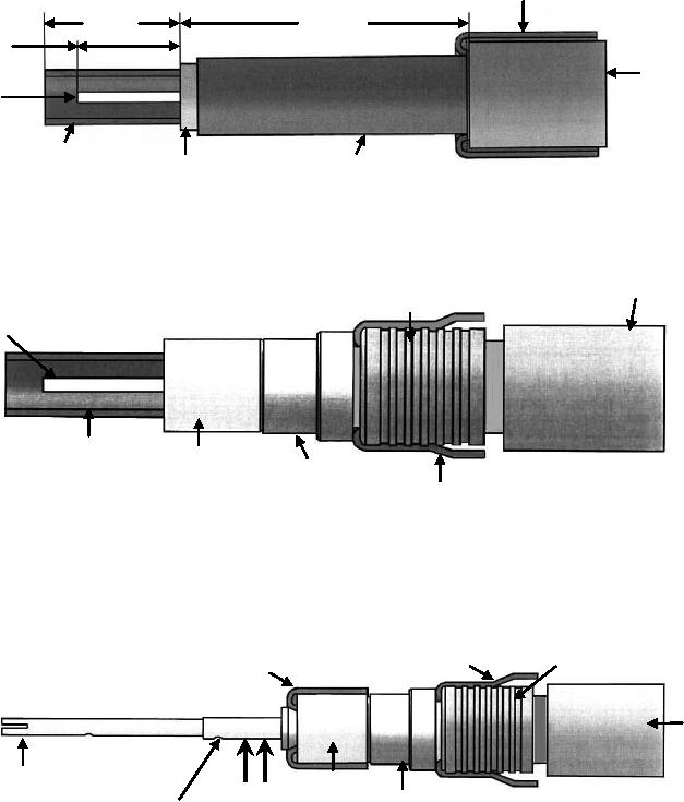
1. Strip cable to dimension shown IAW NAVAIR 01-1A-505-1 WP 009 00. Note 3 shield shown for
nd
reference only, it should be trimmed even with 2 cable jacket.
3rd Shield
0.197"
0.394"
5 mm
10 mm
0.150"
2nd
3.8 mm
Cable
Jacket
Conductor
1st Shield
2nd Shield
1st Cable
Jacket
nd
2. Slide the intermediate contact ferrule over the 2 shield.
nd
3. Fold the 2 shield over the intermediate contact ferrule.
st
st
4. Slide the insulator bushing and 1 contact shield ferrule on 1 cable jacket .
2nd Cable
Intermediate
Contact
Jacket
Ferrule
Conductor
1st
1st
Shield
Insulator
Shield
Bushing
Ferrule
2nd
Shield
st
st
3. Fold back 1 shield over the 1 shield ferrule.
st
4. Slide insulating ring over center conductor till it butts against 1 shield.
5. Slide center contact on center conductor till it butts against insulating ring. Ensure conductor is visible in
the contact inspection hole.
6. Crimp center contact using tools in Table 5 and NAVAIR 01-1A-505-1, WP 013 00.
2nd
1st
2nd Shield
Shield
Shield
Ferrule
2nd Cable
Jacket
Center
1st
Contact
Insulator
Center
Shield
Center
Bushing
Contact
Ferrule
Conductor
Crimp
Visible in
Area
Inspection
Hole
Figure 41. 617190014 and 617090014 Triaxial Contact Buildup (Sheet 1 of 3)