TM 1-6625-476-30
2-29
2-12. CHANNEL BALANCE ADAPTER INSTALLATION. (CONT)
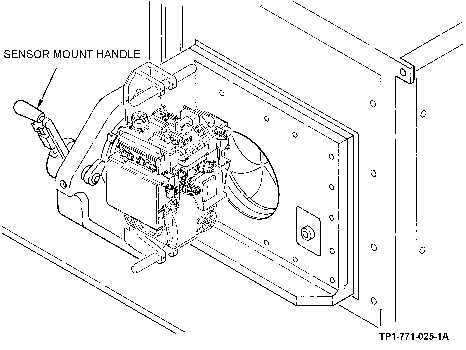
Figure 2-19. Sensor Mount Handle Location
(4) Set torque wrench to 100 in-lb and use torque wrench to tighten clamp assembly. Ensure that
adapter is secured to TADS NSA by checking for no free movement between them.
WARNING
HIGH PRESSURE AIR
Ensure that pneumatic system is shut down. When pneumatic system is
inflated, E/O test bench set is capable of movement. If an attempt is made
to mount TADS NSA with pneumatic system inflated, injury or equipment
damage could occur.
(5) Lift TADS NSA by handles (1, figure 2-22) of channel balance adapter and alive numbered
guide pins (2) with corresponding numbered holes (3) on sensor mount assembly. Ensure
that guide pin (4) on sensor mount assembly is alined with hole (5) in channel balance
adapter.