
TM 55-1650-261-40
accordance with Military Specification MIL-S-6872.
(27), and spring (26) in body (32).
g. Replace all metallic parts exhibiting breaks, cracks, or
c. Install new packing (25) and retainer (24) on
distortion.
solenoid assembly (23). Position solenoid assembly in
body (32).
Note: Minor external nicks and scratches may
d. Position flange (21) over solenoid assembly (23)
and secure to body (32) using screws (22).
be worked smooth with cloth (item 2, table 3).
e. Install new packing (19) on plug (18). Insert
filter (20) in body (32) and install plug.
16. Testing
f. Install packing (17) and retainer (16) in recess of
Apply 18 to 30 vdc to solenoid assembly to determine if
cap (15), and install cap in body (32).
solenoid assembly is in a serviceable condition.
g. Position ring (13) on pilot spool assembly (14).
Insert pilot spool assembly, ring, and spring (12) in body
17. Lubrication
(32).
Lubricate packings and related components with
h. Install new packings (8 and 10) and retainers (7
hydraulic fluid (item 3, table 3) or hydraulic fluid (item 4,
and 9) on cap (11). Install cap in body (32) and secure
with ring (6) and locks (5).
i. Properly place gaskets (3) and spacer (4) on body
18. Reassembly
(32). Extend wire leads through gasket and spacer.
a. Install nameplate (30, figure 3), if removed, and
Solder leads to connector (2) using solder (item 5, table
secure with screws (31).
b. Screw spool-plug assembly (29) onto plunger (28).
Install spool-plug assembly, plunger, locks
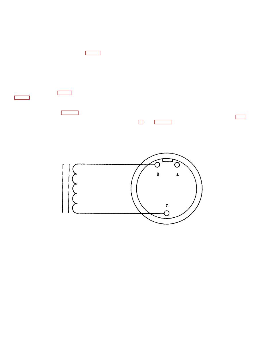
Figure 4. Slide Valve Assembly Wiring Diagram.
j. Properly position connector (1), gaskets (3),
Note: Do not lockwire any hardware until test
and spacer (4) on body (32) insuring holes in parts
procedures have been completed.
align with threaded holes in body and install
screws (2).

