TM 55-2840-254-23
4-66 INSTALL FIRST TURBINE DISC ASSEMBLY (AVIM) (Continued)
4-66
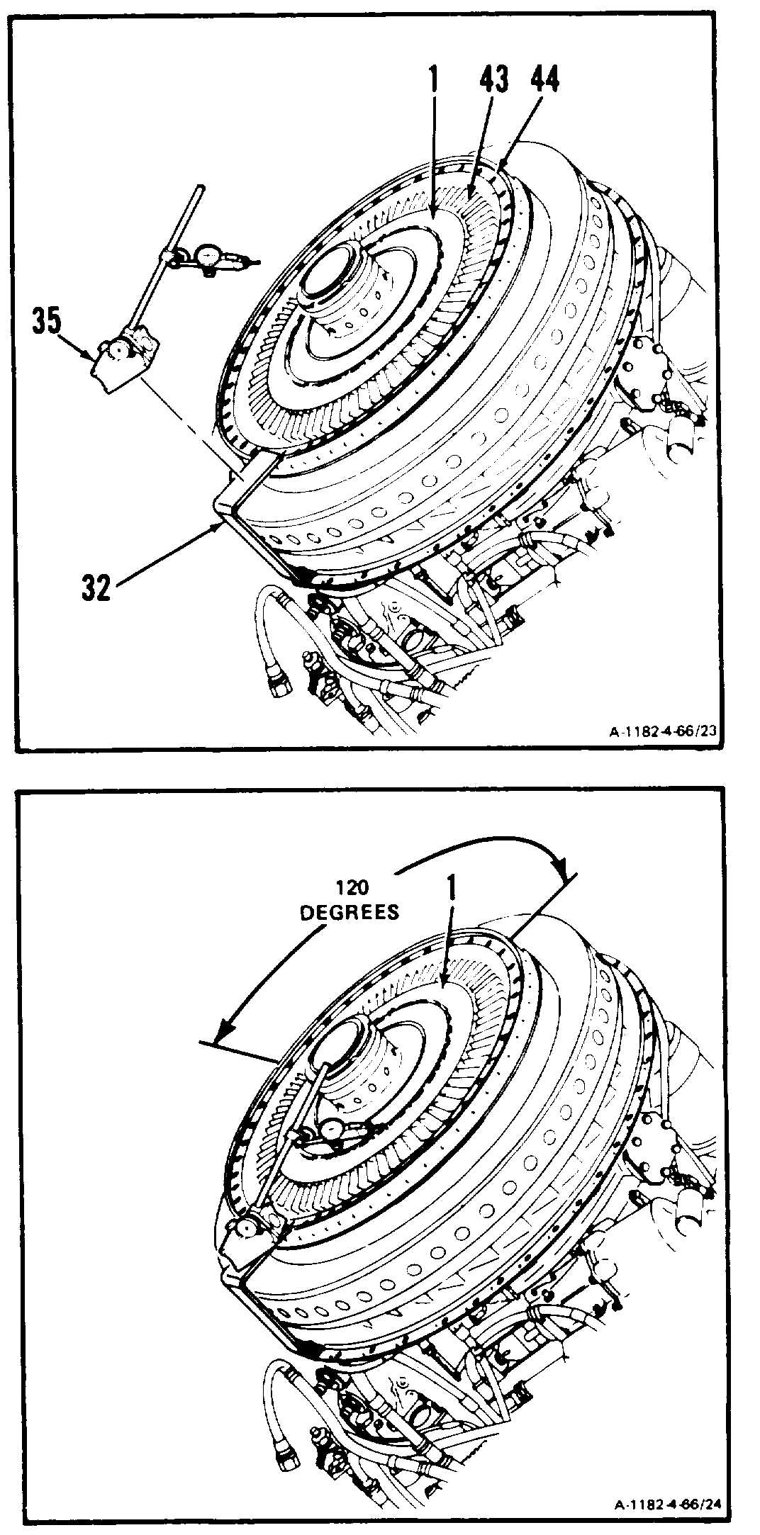
14. Remove dial indicator and bare (35) and sup-
port (32).
15. Hold disc assembly (1) steady. Draw a match-
mark on a blade (43) and flange (44) using
marking pencil (E34).
16. Remove first turbine disc assembly (1) (Ref.
Task 4-62).
If following step brings dimensions with-
in limits, matchmark on compressor shaft
shall be relocated to align with first tur-
bine disc. Failure to comply will result
in out of balance condition of all gas pro-
ducer parts.
17. Install disc assembly (1) rotated approximately
120 degrees. Repeat steps 4. thru 13.
18. If first turbine disc (1) is rotated so match-
marks do not align, erase old matchmark on
compressor shaft. Remark matchmark on com-
pressor shaft to align with matchmark on first
turbine disc (1). Use marking pencil (E34).
19. Rotate engine to vertical position.
GO TO NEXT PAGE
4-426