TB 1-1730-229-30-1
NOTE
Add or remove washers under the flu if necessary to align
exhaust deflector flange with engine mounting flange.
(6) Install (2) MS27130-10 flat washers on 2 front studs in corners of flu base. Install (8) star
washers on all 8 studs. Important, star washers must not extend over the flange of the
deflector. Install (6) modified fender washers on 6 studs such that they extend over the flange
on the exhaust deflector. Install and tighten all eight nuts on the studs. Verify that the deflector
is free to move between the star washers and under the fender washers.
(7) Secure the deflector to the engine using the V-band coupling. Ensure there is no gap
between the engine and exhaust deflector flange.
(8) Install deflector drain tube extension. Replace cover and install screws and washers.
(9) Apply anti-seize compound, (P/N MIL-L-25681) to threads and install the ASP-8
muffler at the surge valve outlet.
(10) Attach pneumatic hose to elbow with hose clamp.
(11) Install elbow on flu and secure with nut.
(12) Replace exhaust access cover using twelve screws and washers.
(13) Install hydraulic module, paragraph 2-8.
7. SUPPLY/PARTS AND DISPOSITION.
a. The current exhaust ejector is no longer stocked. The new improved performance exhaust
installation, P/N 77000-100 (90598), is stocked by DLA (S9C) under the same NSN as the current
exhaust ejector.
b. Existing hardware is used to install new exhaust except for six (6) modified fender washers that
are provided with the assembly.
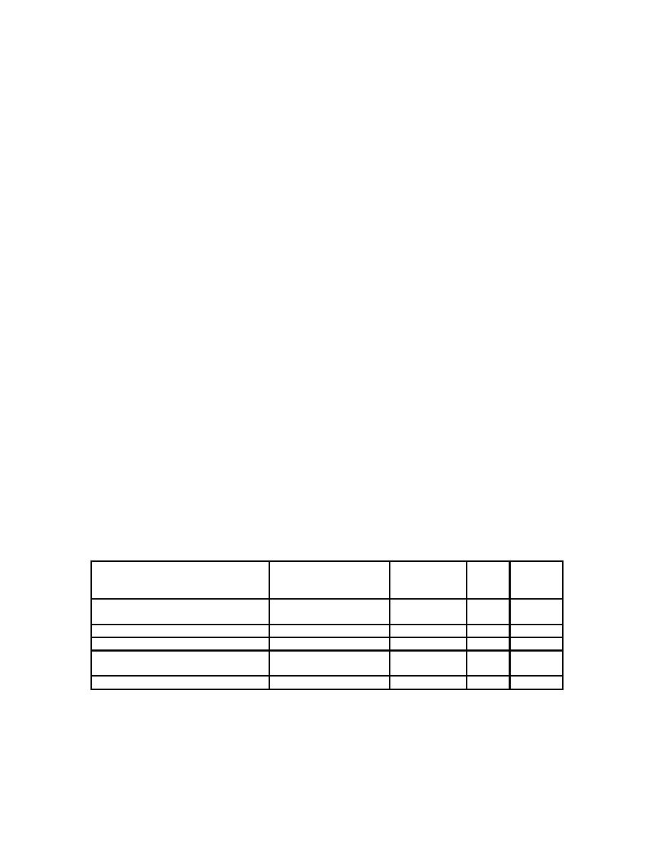
c. The parts/assembles/material are to be requisitioned: (The bleed air exhaust muffler and self-
tapping screw are already installed on all "D" model AGPUs.)
NOMENCLATURE
NATIONAL STOCK
PART
CAGE
QTY
NUMBER
NUMBER
RQD
Exhaust System, Gas Turbine
77000-100
90598
1
Engine
Muffler, Bleed Air Exhaust
4430-01-472-6930
ASP-8
04049
1
Anti-seize Compound
MIL-L-25681
96906
AR
Screw, Self-tapping, 5/16 in.
MS51851-
96906
1
106
Washer, Lock, 5/16 inch
5310-00-407-9566
MS35338-45
96906
1
3


