TM 1-1500-204-23-4
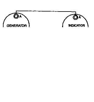
Figure 4-14. Synchronous Rotor Tachometer
Wiring Diagram
(Ungrounded Three-Wire System).
Figure 4-15. Synchronous Rotor Tachometer
Wiring Diagram
(Grounded Two-Wire System).
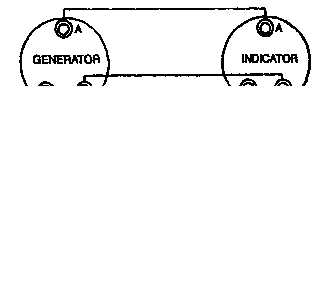
Figure 4-16. Dual Synchronous Rotor Tachometer
Wiring Diagram
(Ungrounded Three-Wire System).
(a) Continuity check test.
Test wiring for
proper continuity as specified in applicable wiring dia-
grams shown in figures 4-14 through 4-17.
(b) Master system test.
Using a field porta-
ble tachometer tester, Type M-5, or equivalent, test gen-
erator and indicator for proper operation. Replace gener-
ator or indicator when test proves either to be
unserviceable.
(c) Zero check test.
With power off, en-
gines not running, indicator needles should not revert to
lowest reading.
k. Electrical Resistance Temperature Indicators
Principles of operation and testing of electrical resistance
temperature indicators are described in the following
paragraphs.
(1) Principles of operation.
The electrical re-
sistance temperature indicator consists of an indicator, a
bulb (located where temperature is to be measured), and
connecting leads.
4-22
Change 3


