
NAVAIR 01-1A-505-2
003 03
TO 00-25-255-1
Page 100
TM 1-1500-323-24-2
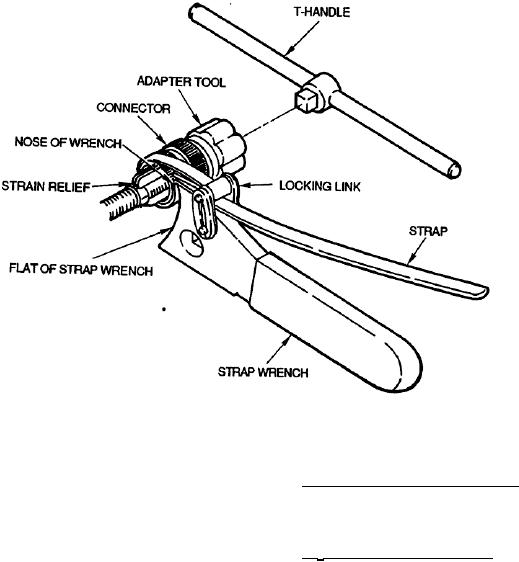
Figure 56. Strap Wrench Setup and Adjustment
f.
Install strap wrench around part to be
103. Straight Strain Relief M85049/38 This is a straight
installed. Draw strap tightly through locking link.
strain relief, The strain relief, along with dimensions
Backshell will rest on nose of wrench (Figure 56).
and part number breakdown, is illustrated (Figure 59).
g. Install T-handle into socket of adapter tool to
104. 90 Strain Relief M85049/39. This is a 90 strain
provide holding (Figure 57).
relief. The strain relief, along with dimensions and part
number breakdown, is illustrated (Figure 60).
h. To tighten backshell apply force clockwise as
viewed from connector rear (Figure 58).
105. STRAIN RELIEF REMOVAL. To remove either
strain relief use the following procedure (Figure 61).
101. STRAIN RELIEFS. Strain reliefs are supports
which attach to the connector and absorb vibration and
a.
Loosen saddle clamp screws.
shock transmitted by the wires or cable to the contact
connection as well as to support cable and wire weight.
b.
Unwrap any reinforcing silicone tape.
102. STRAIN RELIEF AVAILABILITY. Strain reliefs
c.
Remove strain relief using tools and tool
are available in either straight or 90.
procedure for backshell removal (paragraph 21).
d. Perform connector repair per NAVAIR 01-1A-
505-1.