NAVAIR 01-1A-505-2
003 03
TO 00-25-255-1
Page 111
TM 1-1500-323-24-2
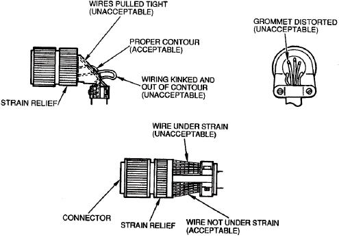
Figure 62. Proper Dress of Wire into Connector
106. STRAIN RELIEF INSTALLATION. Upon the
109. SHRINK BOOT. There is no pre-manufactured
completion of connector repair install the strain relief
shrink boot for these series. Shrink boots should be
using the following procedure (Figure 61):
assembled from MS3118 shrink tube using the
dimensions of the adapter in Figure 63 and the shrink
a. Wrap cable with reinforcing silicone tape to
tube dimensions in Figure 64.
build cable diameter where necessary.
110. SHRINK BOOT AND ADAPTER REMOVAL. To
b. Install strain relief using tools and tool
remove the shrink boot and adapter use the following
procedure for backshell installation (paragraph 22).
procedure:
c.
Restore proper dress of wire at connector. Wire
a. To salvage boot, apply heat using HT-900B
should not elongate grommet holes, pull tightly to
heat gun until pliable.
prevent misalignment (Figure 62).
b. Using a flat screwdriver, gently pry boot from
d. Tighten screws in saddle clamp to provide firm
adapter and wires.
gripping action preventing wire movement without
damage or crushing.
c.
When boot cannot be salvaged, carefully cut
boot from cable.
107. SHRINK BOOT AND ADAPTER. Shrink boots
are protective jackets of heat shrinkable tube that seal
d.
Slide boot away from connector.
to the cable and adapter to prevent moisture entry. The
adapter is a threaded intermediate device which
e.
Remove adapter using tools and procedure
contains a serrated lip to provide a gripping surface
(paragraph 99).
for the shrinkable tube.
f.
Perform connector repair per NAVAIR 01-1A-
108. SHRINK BOOT ADAPTER M85049/69. The
505-1.
shrink boot adapter, along with dimensions and part
number breakdown, is illustrated (Figure 63).

