NAVAIR 01-1A-505-2
010 02
TO 00-25-255-1
Page 9
TM 1-1500-323-24-2
16. POLARIZATION. Connectors are polarized as
denoted by their part numbers. This means that the
master keyway is rotated to prevent mis-mating of
similar connectors in a similar location. A plug with a
given polarization letter will mate with a receptacle
with same letter. The inserts do not rotate, only the
keyway is rotated.
17. PART NUMBER. The following paragraphs contain
information necessary for proper selection and
procurement of connector (Figure 3).
18. Basic Part Number. The prefix denotes the basic
specification.
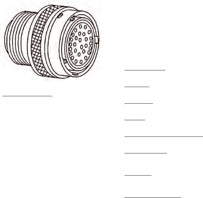
Figure 2. MIL-C-81703 Series I Typical Connector
19. Shell Style. The shell style denotes type and
mounting of connector.
10. MIL-C-81703 SERIES 1.
20. Service Class. The service class is a letter code
11. MIL-C-81703 Series 1 connectors are push-pull
denoting environment resistant ability.
coupled with solder contacts. Series I hermetic box and
solder mount receptacles are also available. The Series
21. Shell Size. Shell size is indicated by a progressive
I connector has a temperature range of -67F (-55C) to
numbering system.
+257F (+125C) (Figure 2).
22. Contact Termination (Hermetics only). The contact
12. GROMMET SEALING PLUGS. The grommets of
indicates type of solder termination.
environment resisting connectors are designed to accept
sealing plugs in accordance with MIL-C-81703 to be
23. Insert Configuration. The insert configuration is the
used where unwired contacts are placed. The connector
insert arrangement by number and size of contacts
when ordered as a unit will have sealing plugs enclosed
used.
to equal 15 percent of the number of contacts but not
less than one.
24. Contact Style. The contact style denotes pin or socket
contacts and whether or not the connector is supplied
13. MATING SEAL. Plugs and receptacles with pin
with contacts.
inserts have a resilient face with individual pin barriers
to seal against the bard face socket insert. The resilient
25. Alternate Keyway Position. The alternate position
interface seal provides individual contact seals in mated
indicates insert polarization (Figure 4).
condition between each contact and shell.
26. DESIGN AND CONSTRUCTION. Connectors and
14. SHELL. Shells including mounting flanges are of
accessories are designed and constructed to withstand
one-piece construction and designed to retain their
normal handling incidental to installation and
inserts in one position by mechanical means. The shell
maintenance.
is designed to accept and retain a cable adapter or other
accessory.
27. CONTACTS. Contact are fixed, non-removable, and
solderable.
15. COUPLING. The two methods of coupling are push-
pull and rack and panel coupling.

