NAVAIR 01-1A-505-3
TO 1-1A-14-3
TM 1-1500-323-24-3
012 02
1 September 2011
Page 3
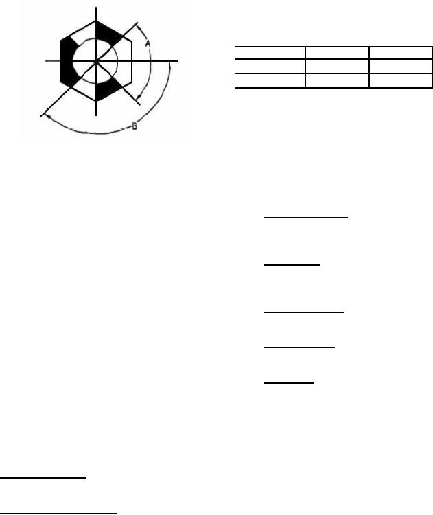
To Polarize Connectors, Boss Is Mounted In The Insulator With The Largest Opening Adjacent To The
Polarization Letter On The Insulator. Two Types Of Bosses Are Used To Prevent 180 Mismating Since
The Contact Arrangements Are Symmetrical.
Polarization
A
B
N, V, W
90
135
X, Y, Z
80
140
Figure 2. SAE AS85028 Polarization Key
9. Insert Configuration. The insert configuration is
NOTE
the insert arrangement by number and size of contacts
used.
As all NAVAIR connector and accessory
documents are transitioned to non-
10. Contact Style. The contact style is indicated by
government standards, (the Society of
letter to show a full complement of applicable
Automotive Engineers (SAE), will become
contacts.
the preparing activity and the Navy will
adopt the documents), the drawing number
11. Contact Designator. The contact designator is a
prefix will change from MS to AS. The main
number which indicates the contact wire barrel size.
part number designation remains the same,
with the "M" prefix, such as M81511/17-08.
12. Center Hardware. The connector center hardware
At times the entire item may be superseded
is designated by a letter.
by another. There are many cases where
documents have been cancelled without
13. Polarization. The connector center hardware
replacements, each case was reviewed and
polarization is designated by a letter (Figure 2).
some information has been retained in this
volume "for reference use only".
14. DESIGN AND CONSTRUCTION. Connectors
and accessories are designed and constructed to
6. PART NUMBER. The following paragraphs
withstand normal handling incidental to installation
contain information necessary for proper selection and
and maintenance.
procurement of connector (Figure 3).
7. Military Designation. The military designation is
15. INTERCHANGEABILITY. All connectors
denoted by the letter M.
having the same part number are completely
interchangeable with each other with respect to
8. Specification Sheet Number. The specification
installation and performance.
sheet number denotes the basic number of the
specification sheet.
16. INSERTS. Inserts are of one-piece construction
and will not chip, crack, or break during assembly or
normal maintenance.

