TM 1-1520-264-23
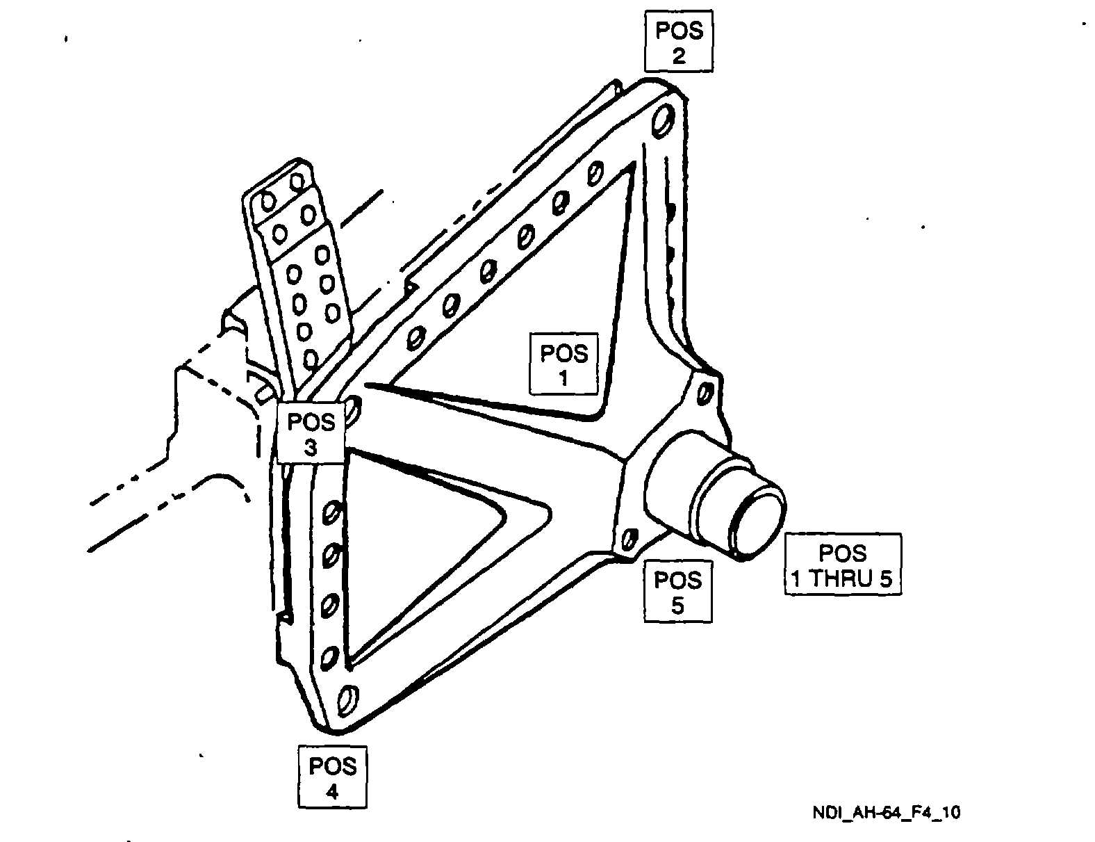
Figure 4-10. Main Landing Gear Shock strut Support
4.10.3.8
Demagnetization. With the switch remaining in the AC position, place the probe/yoke legs in the same
position used for magnetizing. Press the test switch and withdraw the probe/yoke from the part for a distance of two feet
before releasing the switch.
4.10.4 Backup Method. None required.
4.10.5 System Securing. Clean the main landing gear shock strut support thoroughly to remove all residual magnetic
particle media. Refer to Post Cleaning and Restoration of Part or Area After NDI, paragraph 1.4.16. The main landing
gear shock strut support, if removed, requires installation in accordance with the applicable technical manuals listed in
Table 1-1.
4.11
MAIN LANDING GEAR CROSS TUBE MOUNTING POINTS (ET).
4.11.1
Description (Figure 4-1. Index No. 11). The main landing gear cross tube is supported by mounts that are
integral to the helicopter fuselage.
4.11.2 Defects. This inspection is used to verify crack indications found visually on the mounting point area. No cracks
are allowed.
4.11.3 Primary Method. Eddy Current.
4-27