TM 1-1520-264-23
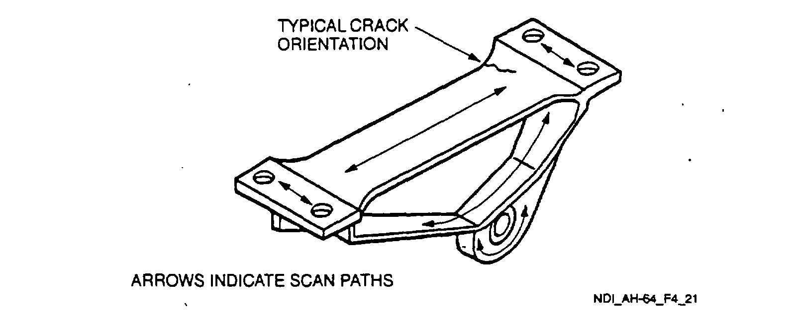
Figure 4-21.
Horizontal Stabilator Actuator Fitting
NOTE
Either probe identified in paragraph 4.21.3.1 may be used depending primarily on the
ease of accessibility and user friendliness. If the probes are changed, steps 4.21.3.5 b.
(1), (2), and (3) shall be repeated each time a change is made.
4.21.3.7
Marking and Recording of Inspection Results. Mark and record the inspection results as required by
paragraph 1.3.
4.21.4
Backup Method. None required.
4.21.5
System Securing. The horizontal stabilator actuator requires installation in accordance with the applicable
technical manuals listed in Table 1-1.
4.22 ENGINE ACCESS AND VENTILATION DOOR ASSEMBLY RIG CONNECTING LINK (PT).
4.22.1
Description (Figure 4-1. Index No. 22)
. The left and right engine ventilation door rig connecting links are the
same. They act to control the air flow into the engine nacelle to assist in controlling engine temperatures.
4.22.2
Defects. This inspection is used to verify crack indications found visually on the connecting links. No cracks
are allowed.
4.22.3
Primary Method. Fluorescent Penetrant.
4.22.3.1
NDI Equipment and Materials. (Refer to Appendix B.) Inspection equipment is listed in Table 1-7. MIL-I-
25135 level 3 penetrant materials shall be selected from the approved list in Table 1-8.
4-51