TM 1-1520-264-23
6.35.3.6
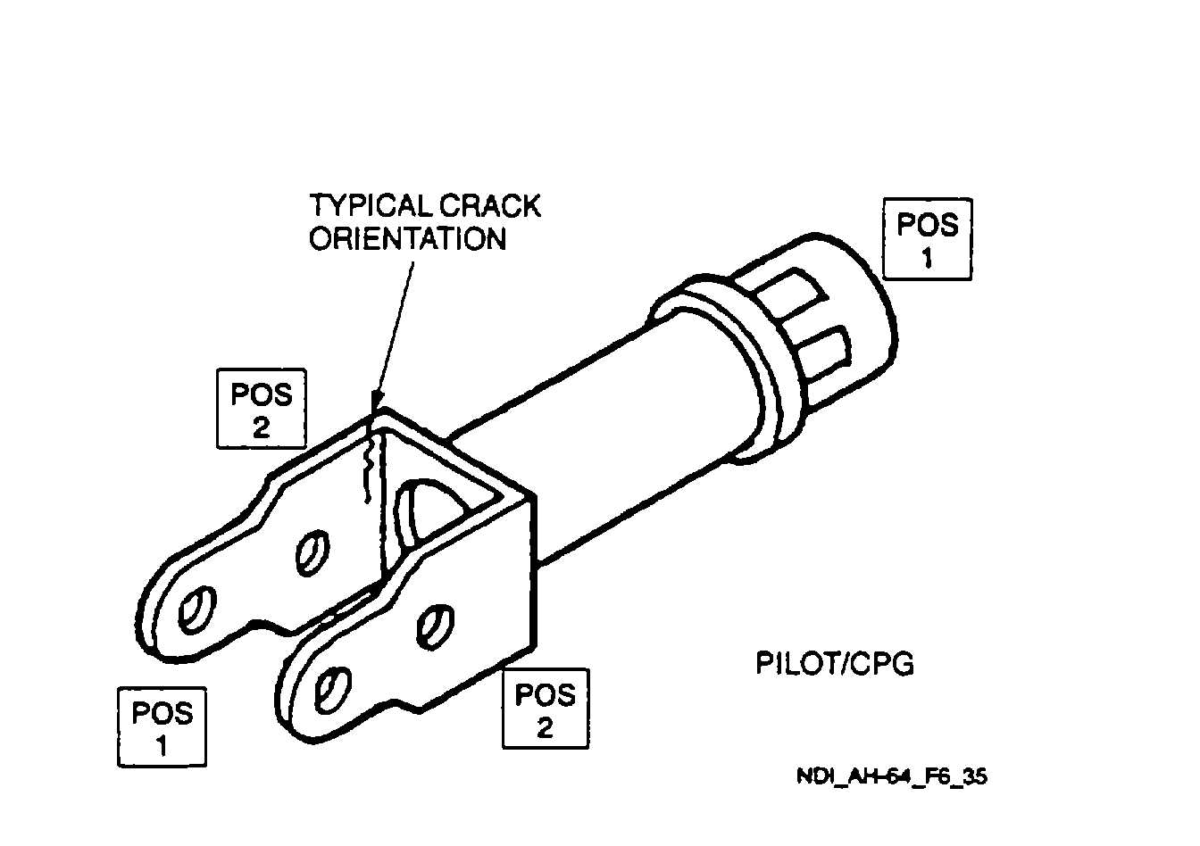
Inspection Procedure. A magnetic field shall be applied to the part perpendicular to the orientation of
possible cracks. Positions required for this inspection are illustrated in Figure 6-35.
a.
Select AC on the AC/DC power switch.
b.
Place probe/yoke on part in position 1 as shown.
c.
Press the test switch and apply a light coat of magnetic particle media at the same time.
Remove the media momentarily before removing the current. Current should be applied for no more than five
seconds.
d.
Inspect for cracks using the black light.
e.
Demagnetize before moving to the next position. Refer to paragraph 6.35.3.8.
f.
Repeat steps a. through e. for position 2.
6.35.3.7
Marking and Recording of Inspection Results. Mark and record the inspection results as required by
paragraph 1.3.
6.35.3.8
Demagnetization. With the switch remaining in the AC position, place the probe/yoke legs in the same
position used for magnetizing. Press the test switch and withdraw the probe/yoke from the part for a distance of two feet
before releasing the switch.
6.35.4
Backup Method. None required.
6.35.5
System Securing. The pilot/CPG directional control pedal release nuts, if removed, require installation in
accordance with the applicable technical manuals listed in Table 1-1.
Figure 6-35. Pilot/CPG Directional Control Pedal Release Nuts
6-76