TM 1-6625-476-30
3-15
3-11. PNVS NSA INSTALLATION ON NIGHTSIDE TEST BENCH. (CONT)
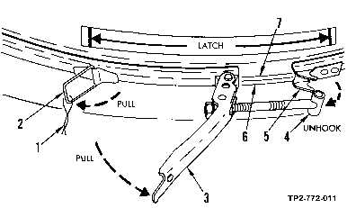
Figure 3-7. Rim Clenching Clamp Removal from PNVS Turret
NOTE
The mark that you made in step (3) will be used to aline shroud to turret
base when shroud is reinstalled.
(4) Remove shroud assembly as follows:
CAUTION
DELICATE EQUIPMENT
Use care when lifting shroud assembly to prevent it from catching on
PNVS NSA components and from scratching optical surfaces. Remove
exactly as instructed.
NOTE
Point (2) in figure 3-8 is bottom surface of shroud balance weight. Point (3)
is surface just below bottom edge of shroud window.
(a) Grasp shroud (1, figure 3-8) at points (2) and (3). Do not press against PNVS window
cover assembly (4).
(b) Lift shroud straight up, approximately 1/2 inch. This action separates shroud from
alinement pins.
(c) Tilt point (2) approximately 20 to 30 degrees, as shown.
(d) With shroud tilted, slowly lift shroud along a sloped path.

