
TM 10-4930-351-14
0002 00
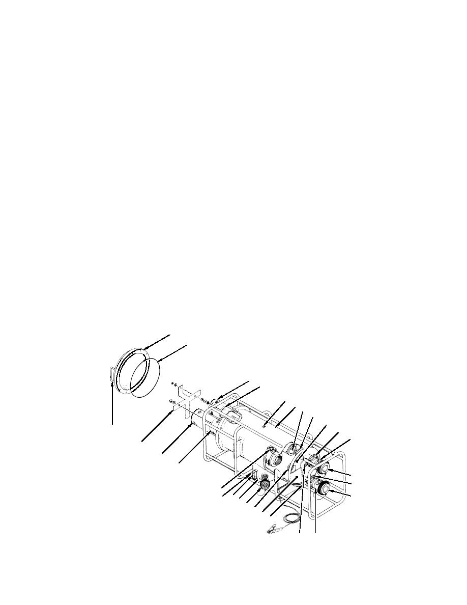
Liquid Fuel Filter-Separator
The liquid fuel filter-separator (figure 3) is an aluminum vessel (1) with an integral frame and is designed to house three
coalescer elements (2) and a separator element (3). A sump (4) at the bottom of the vessel (1) collects water and sediment
removed from the pumpage by the filter action. A diverter plate (5) located directly behind the inlet port (6) prevents the
incoming pressurized pumpage from directly impacting the filter elements (2 and 3) and equalizes pressure across the inlet
bulkhead (7). The coalescer elements (2) are one-piece, closed end, threaded-base elements and are retained to the inlet
bulkhead (7) by threaded-base adapters (8). The separator element (3) is a one-piece, monel or stainless steel screen coated on
both sides with Teflon. It seats over a threaded rod (9) into a friction fit adapter (10) on the inlet bulkhead (7). All four
elements are retained in position at the cover (11) end by a cross shaped element retainer (12). An O-ring (13) and a domed
aluminum cover (11) seal the access end of the vessel (1). Two handles (14) are provided on the cover (11) for removal and
replacement of the cover (11).
3-inch valved unisex couplings (15) bolt to the flanged outlet (16) and inlet (6) ports for interface to the system fuel discharge
hoses. Dust caps (17) are provided to protect the unisex couplings (15) when fuel hoses are not connected. A 2-inch valved
unisex coupling (18) with a pipe thread adapter is fitted to the sump (4) to provide a drain/defuel connection to the system or
an auxiliary pump. A pipe plug (19) located on the bottom of the vessel (1) near the inlet port (6) drains the cavity formed by
the inlet bulkhead (7) and the diverter (5). Air is vented from the module through a manual turn, spring loaded vent valve
(20) located on top of the filter vessel (1). A standard fuel sampling port (21) is fitted into the outlet port (16) for fuel testing.
Filter status is monitored by a sight gauge (22) and a differential pressure gauge (23). The differential pressure gauge (23) is
connected by hard tubing between the inlet (6) and outlet (16) ports to measure the pressure drop across the filter vessel (1).
A clean, properly operating system will register 2-3 pounds differential pressure. The pressure drop will rise gradually as the
elements become contaminated by use. When the pressure reaches fifteen pounds, the coalescer elements (2) should be
changed and the separator element (3) thoroughly cleaned. A sudden drop in pressure indicates that fuel is flowing through
the filter vessel (1) without resistance, probably indicating a ruptured element (2 or 3). A sudden increase in pressure
indicates a blockage due to a malfunction or ingestion of a foreign object. The sight gauge (22) on the vessel sump (4)
provides visual indication of the amount of water collected in the sump (4). A ball in the sight gauge (22) will float on water
but not on fuel, providing a direct indication of the amount of water in the sump (4).
A -turn, inch ball valve (24) on the bottom rear of the sump provides a way to drain accumulated water. The ball valve
can be connected by camlock couplings to a inch, 10 foot hose provided with the filter-separator, allowing the sump to be
drained to any shallow container.
11
13
2
3
20
19
10
7
14
16
15
12
2
2
17
6
23
17
24 22 4
18
8
5
19
15
21
Figure 3. Liquid Fuel Filter-Separator
0002 00-5
