TM 55-1500-345-23
CODE
NO.
DIRECTIONS
WORDING
16
1/2-in. aircraft black letters inside pylon.
REMOVE BONDING JUMPER WHEN DOOR IS TO
BE REMOVED. INSTALL BONDING JUMPER WHEN
INSTALLING DOOR.
17
Below engine nacelles, both sides, aft of air
ENGINE ACCESS
intake screen, 1" aircraft black. Sta 491, WL 52.
FOR FIRE EXTINGUISHER
18
DELETE
19
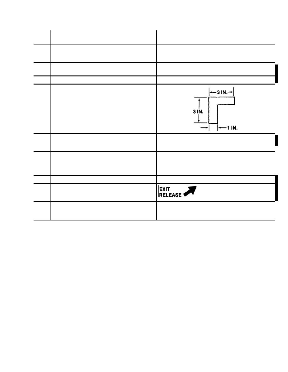
Around emergency exit panels. On both sides
of fuselage and on rear cargo door, Emer. exit
outlines at each corner with corner bands 1 in.
wide and 3 in. long at each leg and painted
aircraft black.
20
Centered under cargo ramp, above emergency
EMERGENCY EXIT
exit, sta 610, 1" aircraft black.
PULL STRAP OUT
PUSH PANEL
21
Top center of engine nacelles between oil filler
LUB OIL
access and oil quantity indicator access doors.
MIL-L-23699 ABOVE -25F
Top of letters facing outbd, 1/2-in. aircraft black
MIL-L-7808 BELOW -25F
letters.
22
DELETE
23
Adjacent to fwd edge of fwd emergency exit.
Left side, sta 119, WL 6. Arrow should point to
pull tab. 1" Aircraft black.
24
PULL TAB
Left side, on bottom corner of emergency exit
OUT PUSH
above pull tab. Aircraft black.
PANEL IN
Figure 9-10. Exterior Markings, CH-47 (Sheet 15 of 29)
Change 11
9-69


