TM55-2840-251-23
APPENDIX D
ILLUSTRATED LIST OF MANUFACTURED ITEMS (Continued)
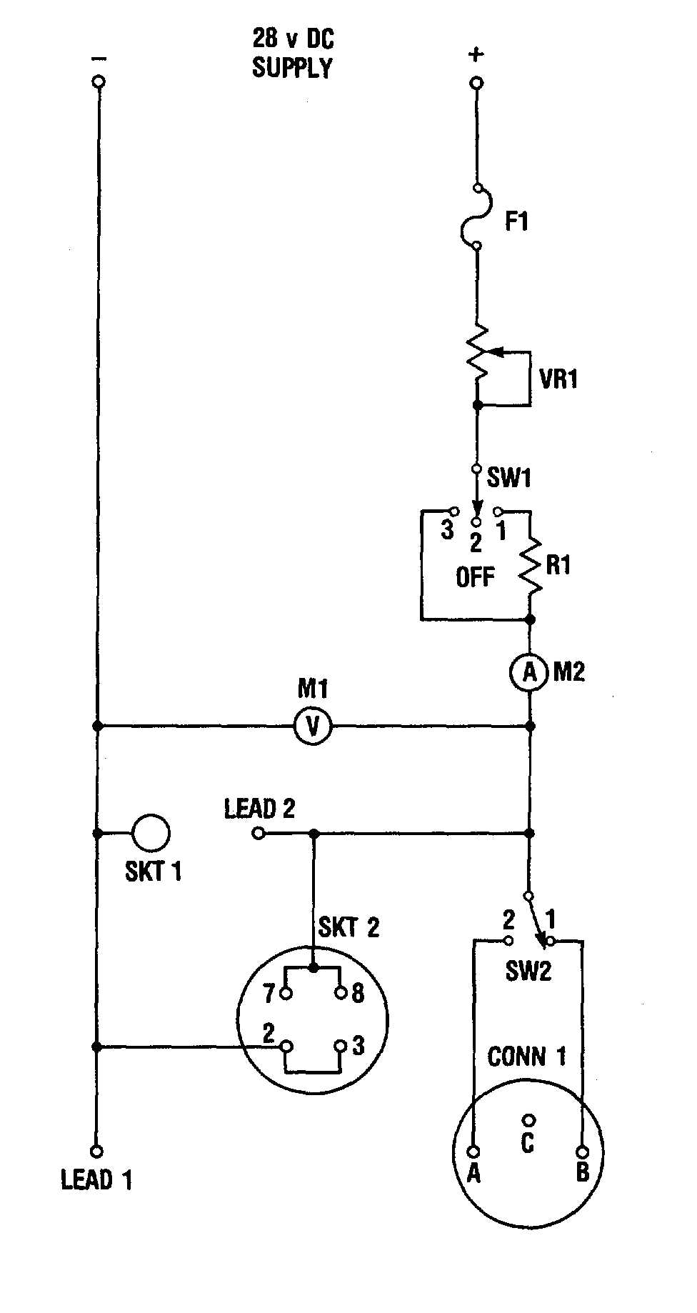
IGNITION TEST SET CIRCUIT DIAGRAM
NOTES
1. All fixed wiring shall be 12 AWG Copper.
2. LEAD 1 and LEAD 2 may be made from one
serviceable ignition lead.
3. SKT 1 is threaded 0.5625-18 UNBG.
4. SKT 2 is NSN 5935-00-891-1470.
5. CONN. 1 is MS3106R 10S 2S.
6. SW1 and SW2 are 10A DC.
7. Fl is 10A fuse or circuit breaker.
8. VR1 is 5 ohm, 10A.
9. R1 is 1 ohm, 10A.
10. M1 is 0-30V DC.
11. M2 is 0-10A DC.
12. Pins 2-3 and 7-8 are common in electron tubes.
Figure D4. Ignition Test Set Circuit Diagram
D--5

