TM 55-2840-254-23
4-10 TEST LEFT- AND RIGHT-HAND BUS BAR ASSEMBLIES
4-10
INITIAL SETUP
Applicable Configurations:
All
Tools:
Multimeter
Materials:
None
Personnel Required:
68B10 Aircraft Powerplant Repairer
Equipment Condition:
Off Engine Task
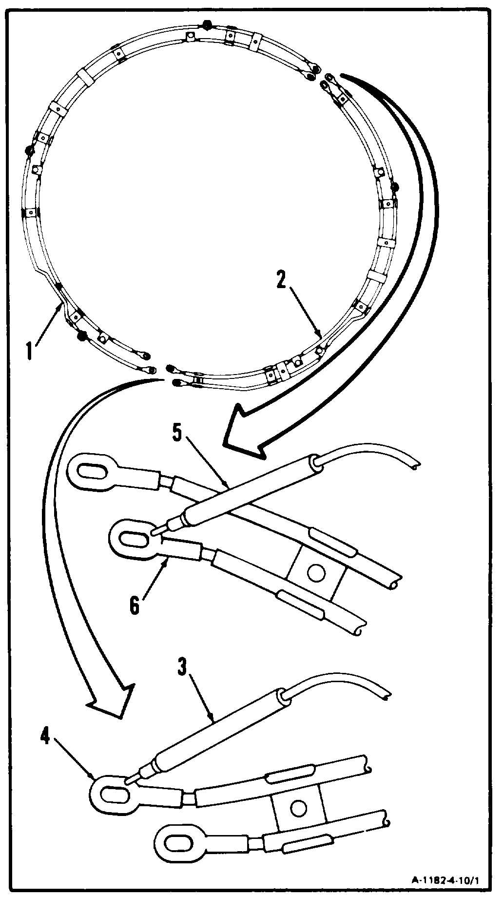
1. Using multimeter, measure continuity of left-
and right-hand bus bar assemblies (1 and 2)
as follows:
NOTE
Following steps a. through g. apply to
both left- and right-hand bus bar assem-
blies. Right-hand bus bar assembly is
shown.
a. Set multimeter range switch to R x 1.
b. Touch red probe (3) to terminal lug (4).
c. Touch black probe (5) to terminal lug (6).
d. Multimeter shall indicate zero ohms. If multi-
meter indicates more than zero ohms, replace
bus bar.
GO TO NEXT PAGE
4-44

