TM 55–2840–254–23
Change 6 4–415
4–66 INSTALL FIRST TURBINE DISC ASSEMBLY (AVIM) (Continued)
4–66
g.
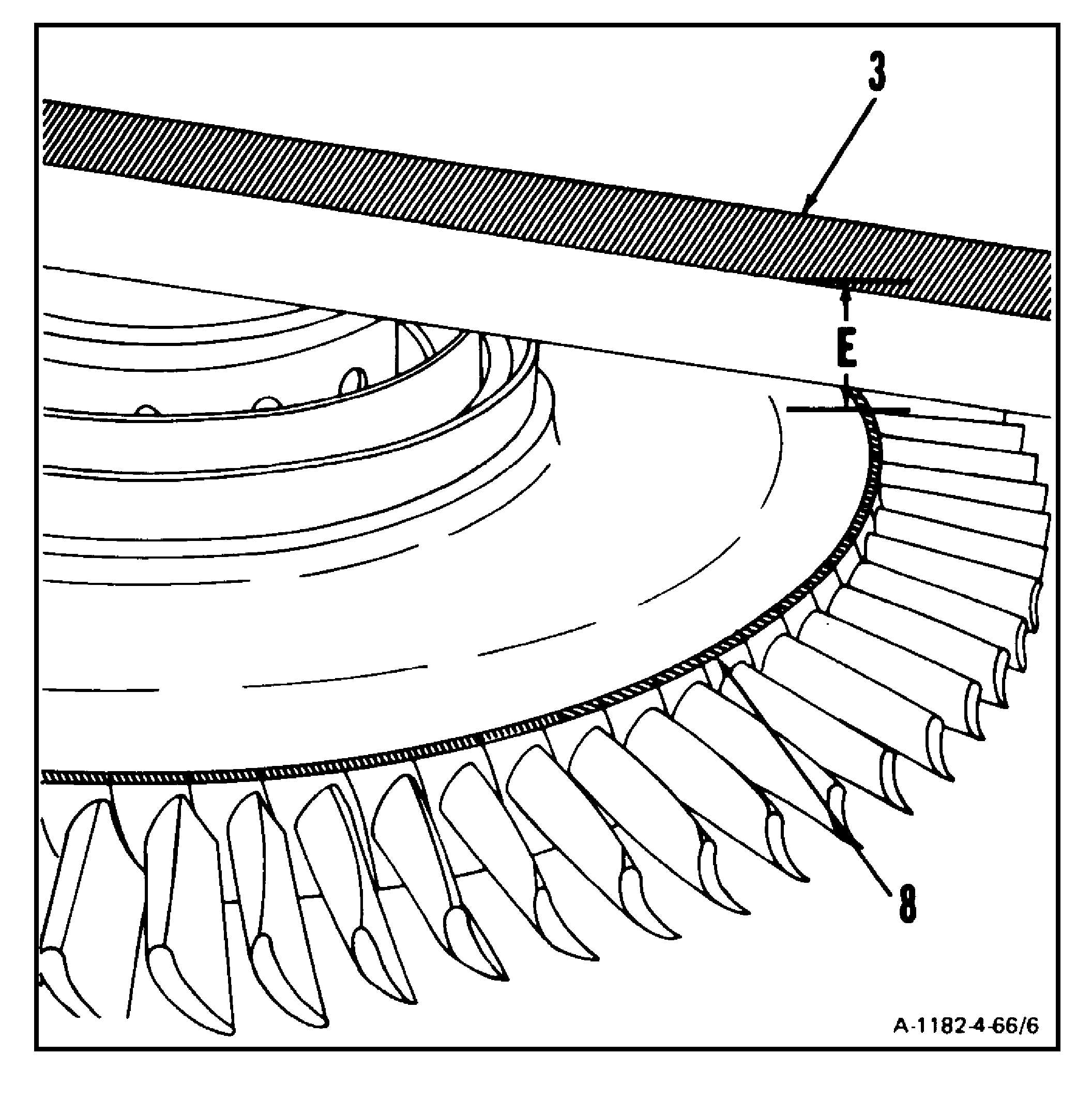
Measure from top of locating bar (T1) (3) to
first turbine disc assembly outer rim (8) in
three places, equally spaced. Average the
three readings. Use micrometer depth
gage. Record as Dimension E.
h.
Subtract Dimension D from Dimension E.
Record as Dimension F.
i.
Subtract Dimension C from Dimension F.
Record as Dimension G.
NOTE
To ensure proper clearance between gas
producer components installed in subse-
quent paragraphs, select shim to obtain
recommended nominal clearance of 0.180
to 0.200 inch. Minimum required clearance
is 0.100 inch.
j.
Subtract Dimension G from 0.100. Select
shim from shim selection table to obtain
0.100 inch minimum. Check shim thick-
ness. Use outside micrometer caliper.
Example: If Dimension G is 0.085 inch, select
Shim Part No. 2–121–089–01. If Dimension
G is 0.050 inch, select Shim Part No.
2–121–089–03.
INSPECT
GO TO NEXT PAGE
SHIM SELECTION TABLE
PART NUMBER
SHIM THICKNESS
2–121–089–01
0.020 inch
2–121–089–02
0.040 inch
2–121–089–03
0.055 inch


