TM 55-4920-428-13
r. Remove the SUPPLY connection cap and the supply hose plug. Connect the supply hose to the
SUPPLY connection.
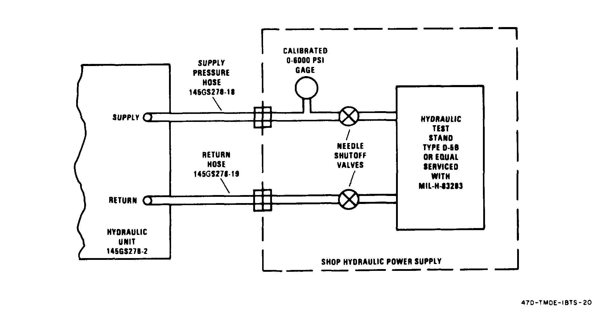
s. Connect the supply hose to the pressure port of the shop hydraulic power supply. The hydraulic
power supply line shall have a needlc type shutoff valve. (See fig. 2-6.)
t. Check that the electrical unit controls are at their initial settings. (Refer to table 2-1.) The SOLE-
NOID SHUTOFF switch, CYCLE MOTOR switch, and FEEDBACK SELECT switches cannot be set
until power is applied. (Refer to para 2-7.)
u. Check that the hydraulic unit valves and controls are at their initial settings. (Refer to table 2-2.)
2-7. SELF TEST Procedures.
Perform the self test of the electrical and hydraulic units as follows:
a. Perform the preparation for use procedures in para 2-6.
b. Set the power switch to ON. Check that SOLENOID SHUTOFF switch is at close, CYCLE MO-
TOR switch is at OFF, and FEEDBACK SELECT switches are at CROSS. (Refer to table 2-1.)
NOTE
The SELF TEST procedure must be accomplished with SAS 1 and SAS
2 cables disconnected, Otherwise, self test indications can be incorrect
c. (See fig. 2-2.) Check that the BITE switch is at -20V and the SYSTEM SELECT switch is at BITE.
The DVM shall indicate -19 to -21.
d. Set the BITE switch to +20V. The DVM shall indicate +19 to +21.
e. Set the BITE switch to –12V. The DVM shall indicate –11 to –13.
Figure 2-6. Hydraulic Unit Operating Setup
2-13