TM 55-2840-254-23
4-32 INSTALLTHIRD TURBINE NOZZLE AND SUPPORT (AVIM) (Continued)
4-32
6.
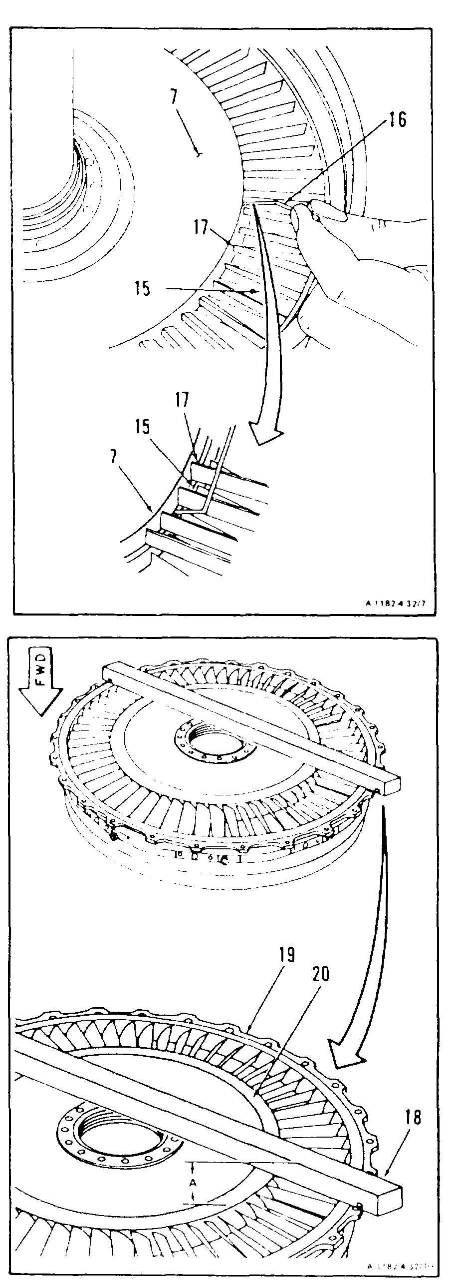
Check for axial clearance between third
turbine rotor (15) and third turbine nozzle
(7). Use 0.101 inch bent wire gage Appendix
E) (16) through third turbine nozzle vanes (17)
Clearance shall be 0.101 inch minimum
6.1
If clearance is not proper, remove third
turbine nozzle and support installed in step 5
and do steps 6.2 and 6.3.
6.2
Determine thickness of sham required to
establish clearance between third turbine
rotor (15) and third turbine nozzle (7) as
follows.
a
Place locating bar (T1) (18) on third turbine
nozzle and support aft flange (19).
b
Measure from top of locating bar
(T1) (18) to trailing edge of inner shroud of
third turbine nozzle assembly (20) Use a
micrometer depth gage Record as
Dimension A.
GO TO NEXT PAGE
4-148 Change 2