TM 1-1500-204-23-1
(b)
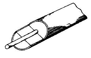
Fenwal system. The Fenwal
system, as shown in figure 9-34, uses a single wire
surrounded by a continuous string of ceramic beads in an
Inconel tube. The beads in the Fenwal detector are
wetted with a eutectic salt which possesses the
characteristic of suddenly lowering its electrical resistance
as the sensing element reaches its alarm temperature.
c.
Maintenance of Fire Detection Systems. Inspect
fire detection systems for the following:
•
Cracked or broken sections caused by crushing
or squeezing between inspection plates, cow
panels, or engine components.
•
Abrasion caused by rubbing of element on
cowling, accessories, or structural members
•
Pieces of safety wire or other metal particles
which may short the spot detector terminals.
•
Condition of rubber grommets in mounting
clamps, which may be softened from exposure
to oils, or hardened from excessive heat
•
Dents and kinks In sensing element sections
Figure 9-34. Fenwal Sensing Element
NOTE
Limits on the element diameter,
acceptable
dents
or
kinks,
and
degree of smoothness of tubing
contour
are
specified
by
manufacturers. No attempt should
be made to straighten any acceptable
dent or kink, since stresses may be
set up that could cause tubing
failure.
•
Loose nuts or broken safety wire at the end of
the sensing elements
NOTE
Loose nuts should be re-torqued to
the
value
specified
in
the
manufacturer's instructions. Some
types
of
sensing
element
connections
require
the
use
of
copper
crush
gaskets.
These
gaskets should be replaced any time
a connection is separated
•
Broken or frayed flexible leads, if used.
NOTE
The flexible leads is made up of
many fine metal strands woven into a
protective covering surrounding the
inner insulated wire. Continuous
bending of the cable or rough
treatment can break these fine wires,
especially those near the connectors
Broken strands can also protrude
into the insulated gasket and short
the center electrode.
•
Proper sensing element routing and clamping.
NOTE
Long unsupported sections may
permit excessive vibration which can
cause
breakage.
The
distance
between clamps on straight runs is
usually about 8 to 10 inches, and is
specified by each manufacturer. At
end connectors, the first support
clamp is usually located about 4 to 6
inches from the end connector
fittings. In most cases, a straight run
of 1 inches is maintained from all
connectors before a bend is started,
and an optimum bend radius of 3
inches is normally adhered to
9-35