TM 1-1500-204-23-2
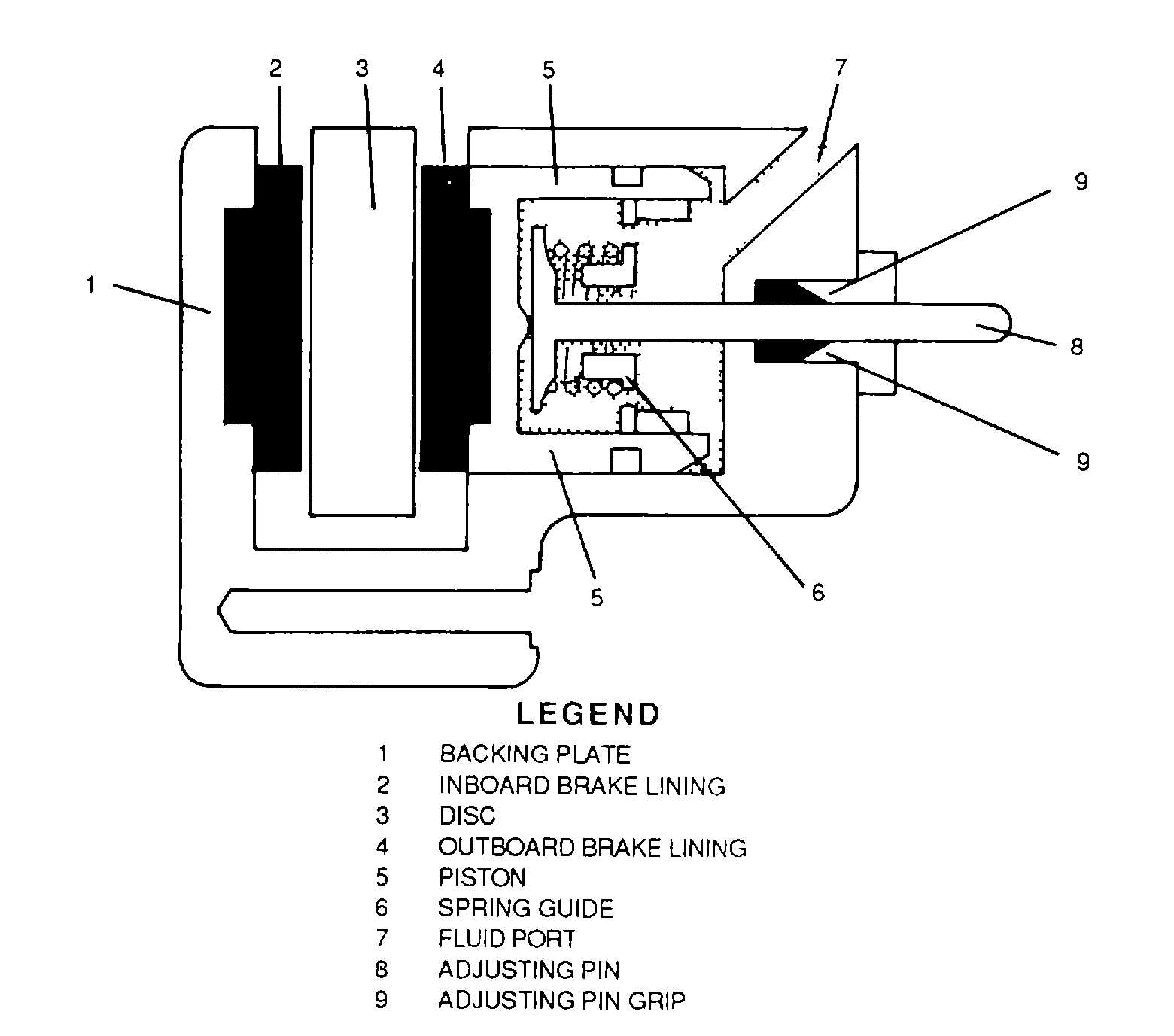
Figure 4-155. Disc Brake Assembly Cross Section
changes or minor leakage. During normal braking of the aircraft by pedal actuation, the lever of the parking brake valve
is held in the off position by means of a spring. The camshaft to which the lever is attached holds the two outer poppets
of the valve unseated as shown here. This permits fluid pressure from the master cylinder or power brake control valve
to pass straight through the parking brake valve to the wheel brake assemblies. In this position, the inner poppets are
seated and the spring-loaded pistons are inoperative.
(b)
Setting parking brakes. To set the brakes for parking, the parking brake valve is left in
the off position until the brake pedals are depressed (see figure 4-157). While the brake pedals are still depressed, the
parking brake control handle is pulled to the park position. This rotates the camshaft of the valve, causing the outer
poppets to seat as shown in figure 4-158, fluid pressure is now locked within the wheel brake assemblies. At the same
time, the rotating camshaft unseats the inner poppets, thereby opening the compensator cylinders to the wheel brake
assemblies. As a result, the compensator cylinders become charged, the pistons become partially retracted, and the
springs become partially compressed. Spring tension on the spring-loaded pistons maintains constant braking pressure
by compensating for volume changes produced by changes in temperature and by minor leaks.
(c)
Brakes locked. After the parking brake has been set in the park position, the brake
pedals are released. The parking brake lever then becomes locked in the park position by means of a locking pin, which
is extended to the locking position by a spring. The locking pin is retracted, permitting release of the lever by fluid
pressure, when the brake system is pressurized by operating the brake pedals.
c.
Helicopter Rotor Brake Systems. Rotor brake systems are Installed on some helicopters as a means of
shortening the time required to bring their rotor assemblies to rest after power has been shut off. They also prevent the
rotor assemblies of parked helicopters from windmilling. A basic hydraulic rotor brake system is shown in figure 4-159.
Newer helicopters have more complex systems, but the same basic principles apply.
4-150