TM 1-1500-204-23-4
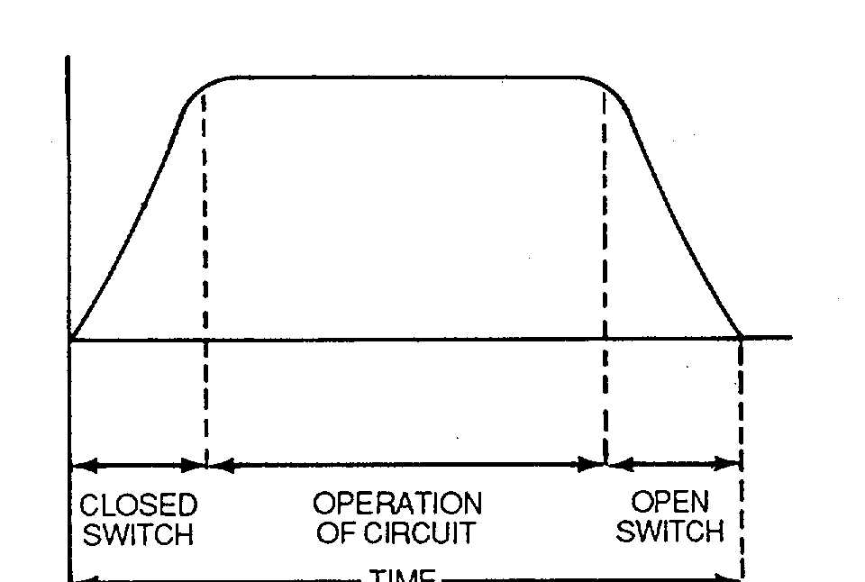
Figure 2-1. Direct Current Wave Form
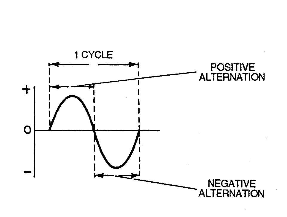
Figure 2-2. Alternating Current Cycle
the positive terminal of the battery. It provides only one
possible path for current to flow. Current flow passes
through circuit components, battery, and resistor, one
after the other, or in series.
b.
Parallel. A circuit in which two or more electrical
resistances, or loads, are connected across the same
voltage source, as shown in figure 2-6, is a parallel circuit.
The parallel circuit differs from the series circuit in that
more than one path is provided for current flow. The
minimum requirements for a parallel circuit are the
following:
·
A power source.
·
Conductors.
·
A resistance or load for each current path.
·
Two or more paths for current flow.
c.
Compound. A compound circuit is a combination
of series and parallel circuits. A series-parallel circuit
consists of groups of parallel resistors. An example of a
series-parallel circuit is shown in figure 2-7. The
requirements for a series-parallel circuit are as follows:
·
Power source (battery).
·
Conductors (wires).
·
Load (resistances).
·
More than one path for current flow.
·
A control (switch).
·
Safety device (fuse).
2-6. Measuring Equipment. Various lights, testers, and
meters used to measure electrical values are explained in
the following paragraphs.
a.
Test Lights. Test lights consist of ordinary low
voltage incandescent lamps, neon lamps or headsets, and
a pair of leads for connecting the indicator to the circuit to
be tested. These testers are simple pieces of test
equipment used to. check the continuity of fuses and line
circuits. These testers do not give accurate qualitative
measurements such as can be obtained with a meter.
However, their simplicity is of considerable advantage
when open and closed circuit tests are made. The neon
and lamp testers also can be used to distinguish between
ac and dc supplies and to test capacitors. In some testers
a switching arrangement allows a source of voltage to be
inserted in series with the test lamp, so that circuits with
no voltage applied to them can be checked.
b.
Continuity Tester. A continuity tester uses the
constant-current
circuitry
of
a
multimeter
for
measurements of resistance. It can be used to check for
opens, shorts, or grounds, as shown in figure 2-8.
c.
D'Arsonval Meter
. The D'Arsonval meter, as
shown in figure 2-9, is a dc galvanometer consisting of a
narrow rectangular coil suspended between the poles of a
permanent magnet. The D'Arsonval meter movement is
a current measuring device which is used in ammeters,
voltmeters, and ohmmeters. The D'Arsonval meter is
being phased out by digital measuring equipment.
2-3