TM 1-1500-204-234
b.
Replacement Criteria. Wiring shall be replaced
when found to have any of the following defects:
·
It becomes unmanageable due to splice or number of
splices.
·
The primary insulation has been broken.
·
The outer insulation is weather-cracked.
·
It is known to have been exposed to battery acid or
the insulation is beginning to deteriorate due to
suspected exposure to battery acid.
·
It shows evidence of overheating.
·
The insulation has been saturated with engine oil,
landing gear lubricant, hydraulic fluid, or solvent.
·
It shows evidence of having been crushed or severely
kinked.
CAUTION
Cleaning agents or preservatives
shall not be used to minimize the
effects
of
corrosion
on
or
deterioration
of
wire
shields.
Further damage may occur.
·
The metallic shield on shielded wire is frayed or
corroded.
·
The insulation sleeves placed over wire splices or
terminal lugs show evidence of breaks, cracks, dirt, or
moisture.
c.
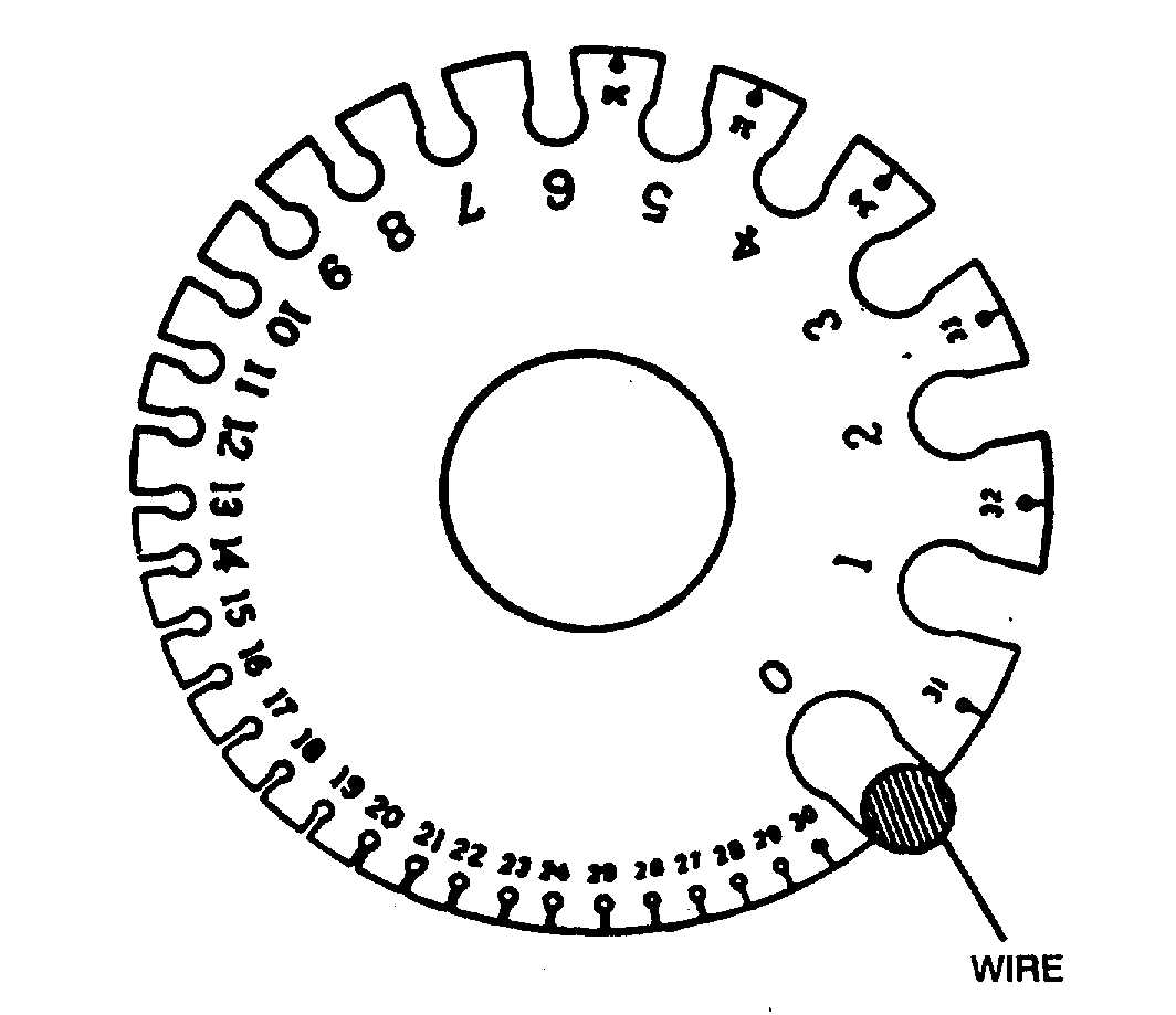
Wire Sizes. Wire is manufactured in sizes
according to a standard known as the American Wire
Gauge (AWG). Wire size may be determined by using a
wire gauge as shown in figure 3-1. This type of gauge will
measure wires ranging in size from number 0 to number
36. The wire to be measured is inserted in the smallest
slot that will just accommodate the bare wire. The gauge
number corresponding to that slot indicates the wire size.
The slot has parallel sides and should not be confused
with the semicircular opening at the end of the slot. The
opening simply permits the free movement of the wire all
the way through the slot.
Figure 3-1. Wire Gauge
NOTE
Gauge
numbers
are
useful
in
comparing the diameter of wires,
but not all types of wire or cable
can be accurately measured with a
gauge. Large wires are usually
stranded to increase their flexibility.
In such cases, the total area can be
determined by multiplying the area
of one strand (usually computed in
circular mils when diameter or
gauge number is known) by the
number of strands in the wire or
cable.
d.
Wire Identification. To make maintenance easier,
each interconnecting wire and cable installed in aircraft is
marked with a combination of letters and numbers which
identify the wire, the circuit it belongs to, its gauge size,
and other information necessary to relate the wire to a
wiring diagram. This marking is called the cable
identification code. Details of the code are given in MIL-
W-5088. Wire received from the manufacturer is printed
with the manufacturer's code designation is a light green
color at intervals of one to five feet, the MS number and
dash number of the wire, and a one-, two-, or three-digit
number indicating the color of the basic wire insulation
and the color of the stripes (if present). The color code is
as follows:
Black
0
Blue
6
Brown
1
Violet
7
Red
2
Gray
8
Orange
3
White
9
Yellow
4
(includes also
Green
5
uncolored insulations)
Change 3
3-3