
NAVAIR 01-1A-505-2
006 03
TO 00-25-255-1
Page 3
TM 1-1500-323-24-2
14. Military Prefix. The military prefix denotes military
standard.
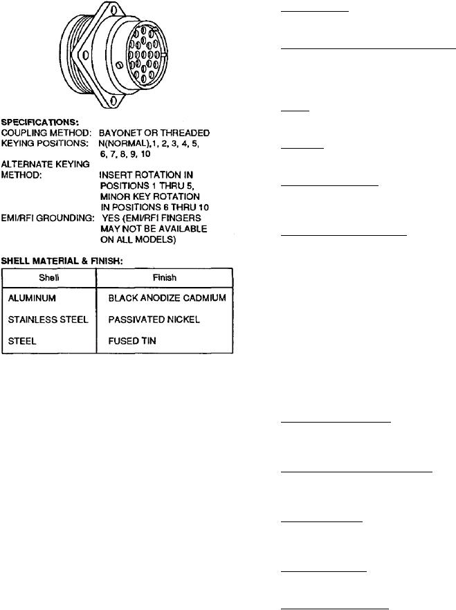
15. Shell Coupling and Contact Style. The shell,
coupling, and contact style denotes type of connector,
coupling (bayonet or threaded) and contact style (pin
or socket).
16. C l a s s . T h e c l a s s i s a l e t t e r c o d e d e n o t i n g
environment resisting ability.
17. Shell Size. The shell size is indicated by a progressive
numbering system.
18. Insert Configuration. The insert configuration is
the insert arrangement by number and size of contacts
used.
19. Alternate Keyway Position. The alternate position
indicates insert polarization (Figure 3).
20. DESIGN AND CONSTRUCTION. Connectors and
accessories are designed and constructed to withstand
normal handling incidental to installation and
maintenance (Figure 4).
21. INSERTS. The non-resilient material used for all
inserts shall be a high grade dielectric having electrical
and mechanical characteristics suitable for the purpose
intended. The impact strength shall be such that
Figure 1. MIL-C-83723 Series III Typical Connector
material shall not chip, crack, or break during assembly
or normal maintenance.
10. SHELL. Shells including mounting flanges are of
one-piece construction and designed to retain their
22. Crimp Snap-in Contacts. Snap-in contacts designed
inserts in one position by mechanical means. Each plug
to AS39029 can be crimped with standard M22520/1
and receptacle has at least one blue color band, which
crimp tool.
indicates rear release retention system, and is located
to be readily visible.
23. Closed-Entry Socket Contacts. These contacts
eliminate damage from abuse by test probes and help
11. COUPLING. Connectors shall be capable of being
to correct any misaligned pins during engagement.
fully coupled and uncoupled without use of tools.
24. Contact Insertion. Insertion is accomplished from
12. POLARIZATION. Connectors are polarized as
rear of connector. When contact is fully inserted, the
denoted by their part numbers. This means that the
clip tines snap securely behind contact shoulders.
master keyway is rotated to prevent mis-mating of
similar connectors in a similar location. A plug with a
25. Contact Extraction. Extraction is accomplished with
given polarization letter will mate with a receptacle
use of a removal tool.
with same letter. The inserts do not rotate, only the
keyway is rotated.
26. Contact Retaining Clip. The contact retaining clip
is completely encased in a tough plastic wafer to protect
13. PART NUMBER. The following paragraphs contain
clip from damage.
information necessary for proper selection and
procurement of connector (Figure 2).