
NAVAIR 01-1A-505-2
008 02
TO 00-25-255-1
Page 3
TM 1-1500-323-24-2
NOTE
As all NAVAIR connector and accessory
documents are transitioned to non-government
standards, (the Society of Automotive
Engineers (SAE), will become the preparing
activity and the Navy will adopt the
documents), the drawing number prefix will
change from MS to AS. The main part number
designation remains the same, with the "M"
prefix, such as M81511/17-08. At times the
entire item may be superseded by another.
There are many cases where documents have
been cancelled without replacements, each case
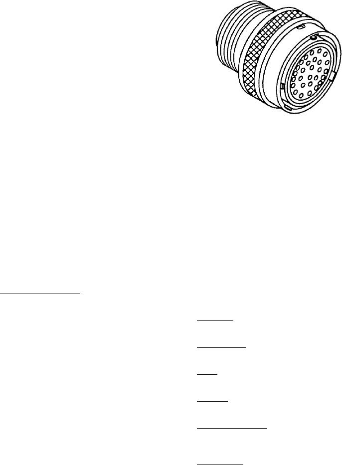
Figure 1. MIL-C-26482 Series 1 Typical Connector
was reviewed and some information has been
retained in this volume "for reference use only".
10. SHELL. Shells including mounting flanges are of
one-piece construction and designed to retain their
3. DESCRIPTION. MIL-C-26482 connectors utilize
inserts in one position by mechanical means.
crimp type contacts or non-removable solder contacts.
Crimp type contacts are front release or rear release but
11. COUPLING. Connectors shall be capable of being
both are inserted and removed from rear of connector.
fully coupled and uncoupled without use of tools.
4. All MIL-C-26482 connectors are environment
12. POLARIZATION. Connectors are polarized as
resisting, quick disconnect, miniature, circular electrical
denoted by their part numbers. This means that the
connectors. Series 1 and 2 connectors are intermateable
master keyway is rotated to prevent mis-mating of
when using power contacts, and are not intermateable
similar connectors in close proximity to each other, or
when using shielded contacts.
in a similar location. A plug with a given polarization
letter will mate with a receptacle with same letter, The
5. WIRE SEALING. Wire sealing is accomplished by
inserts do not rotate, only the keyway is rotated.
the use of a grommet seal which is designed to seal
against outside diameter of inserted wire.
13. PART NUMBER. The following paragraphs contain
6. MIL-C-26482 SERIES 1.
information necessary for proper selection and
procurement of connector (Figures 2 and 3).
7. The MIL-C-26482 Series 1 connectors are bayonet
coupled with solder or front release crimp removable
14. Shell Style. The shell style denotes the type and
contacts. Hermetic receptacles have solder contacts
mounting of connector.
(Figure 1).
15. Military Prefix. The military prefix denotes military
8. GROMMET SEALING PLUGS. The grommets of
standard.
environment resisting connectors are designed to accept
sealing plugs in accordance with MIL-C-26482 to be
16. C l a s s . T h e c l a s s i s a l e t t e r c o d e d e n o t i n g
used where unwired contacts are placed. The connector,
environment resisting ability.
when ordered as a unit, will have sealing plugs enclosed
to equal 15 percent of the number of contacts but not
17. Shell Size. The shell size is indicated by a progressive
less than one.
numbering system.
9. MATING SEAL. Plugs and receptacles with pin
18. Insert Configuration. The insert configuration is
inserts have a resilient face with individual pin barriers
the insert arrangement by number and size of contacts
to seal against the hard face socket insert. The resilient
used.
interface seal provides individual contact seals in mated
condition between each contact and shell.
19. Contact Style. The contact style denotes type of
contact used.