
NAVAIR 01-1A-505-2
008 02
TO 00-25-255-1
Page 7
TM 1-1500-323-24-2
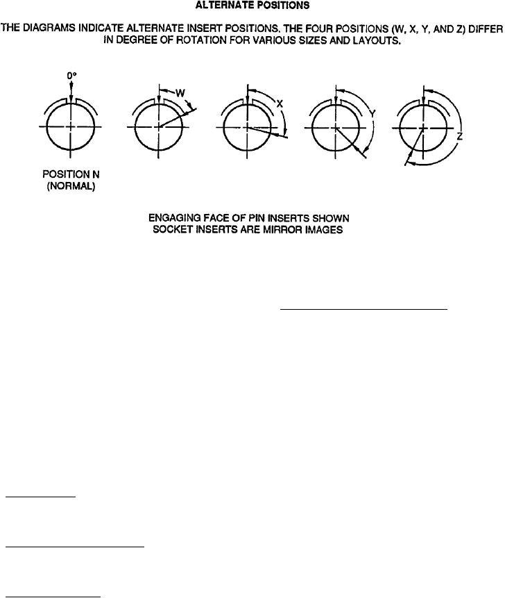
Figure 5. MIL-C-26482 Series 1 and 2 Alternate Key Positions
41. Installation and Removal Tools. The proper
35. INSERT ARRANGEMENT. The insert arrangement
installation and removal tools must be used to assemble
is the number and size of contacts available by shell
or disassemble connectors. The connector, when
size (Table 1). Insert arrangements are specified in
ordered as a unit package, will include one MIL-I-
MIL-STD-1669.
81969/17 tool.
36. I N S E R T C O N F I G U R A T I O N . T h e i n s e r t
42. CONTACT APPLICATION. Contacts used are
configuration is the manner in which contacts are
manufactured in accordance with AS39029. The contact
placed within the insert in a standard configuration.
part number breakdown is illustrated (Figure 7). The
All arrangements identified in Table 1 are illustrated
Basic Identification Number (BIN) or last three digits
(Figure 6).
of contact part number, matches the standard resistor
color code (Figure 8).
37. CONTACTS. Contacts are designed to prevent
damage to contact retention device or sealing member
43. POWER CONTACTS. Power contacts are used to
during insertion or removal of contacts.
connect single conductor wire through connectors.
38. Fixed Contacts. Contacts in hermetically sealed or
The power contacts range from size 8 through 20 and
thru-bulkhead receptacles are fixed non-removable,
are of crimp, front release design. Contacts are listed by
and solderable, or feed through type.
size. Match the required size to connector application,
wire gage, and composition. Socket and pin contact
39. Crimp Removable Contacts. Crimp removable
part numbers are listed along with corresponding color
contacts may be used with all environment resisting
bands (Table 2).
classes of connectors.
44. TOOLING. The procedure for attaching power
40. Contact Availability. Crimp contacts are supplied
contacts to a single conductor wire are the same for this
with each connector unit package and consist of a full
connector series. Select the proper tooling for the specific
complement plus one spare per size for connectors of
contact part number (Table 3) and refer to NAVAIR
26 contacts or less. Connectors with more than 26
01-1A-505-1, WP 013 00 for correct assembly and crimp
contacts will have two spares of each size used. Contacts
procedures.
may also be ordered in individual quantities when
necessary.