
NAVAIR 01-1A-505-2
009 02
TO 00-25-255-1
Page 5
TM 1-1500-323-24-2
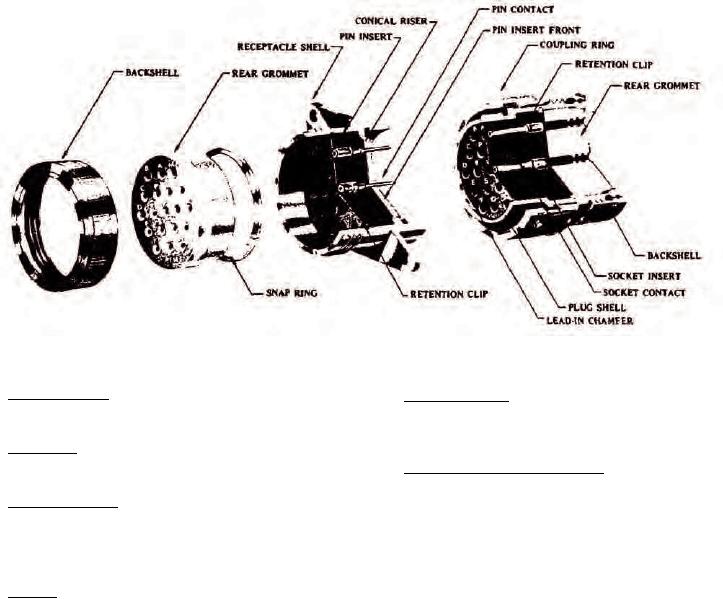
Figure 3. Design Features
30. Interfacial Seal. This seal is achieved by insulator
37. Fixed Contacts. Contacts in hermetically sealed
faces meeting when the plug and receptacle are mated.
receptacles are fixed non-removable, and solder-able,
or feed through.
31. Wire Seal. The wire seal is accomplished by a
multiple ripple design.
38. Crimp Removable Contacts. Crimp removable
contacts may be used with all environment resisting
32. Insert Retention. Insert retention is accomplished
classes of connectors.
by a hard plastic wafer firmly locked into a groove in
shell, in addition a strong adhesive bond is used
39. CONTACT APPLICATION. Contacts used are
between insert and shell.
manufactured in accordance with AS39029. The contact
part number breakdown is illustrated (Figure 6). The
33. Keying. Keying is used in shell-enclosed connectors
Basic Identification Number (BIN) or last three digits
to obtain polarization, which assures correct location
of contact part number, matches standard resistor
when mating a connector (Figure 4).
color code (Figure 7).
34. I N S E R T A R R A N G E M E N T S . T h e i n s e r t
40. POWER CONTACTS. Power contacts are used to
arrangement is the number and size of contacts
connect single conductor wire through connectors.
available by shell size (Table 1). Insert arrangements
The power contacts range from size 12 through 20 and
are specified in MIL-STD-1554.
are of rear insertion, front release design. Contacts are
listed by size. Match the required size to connector
35. I N S E R T C O N F I G U R A T I O N . T h e i n s e r t
application, wire gage, and composition. Socket and
configuration is the manner in which the contacts are
pin contact part numbers are listed along with
placed within the insert in a standard configuration.
Corresponding color bands (Table 2).
All arrangements identified in Table 1 are illustrated
(Figure 5).
41. TOOLING. The procedures for attaching power
contacts to a single conductor wire are the same for
36. CONTACTS. Contacts are designed to prevent
this connector series. Select proper tooling for specific
damage to contact retention device or sealing member
contact part number (Table 3) and refer to NAVAIR
during insertion or removal of contacts.
01-1A-505-1, WP 013 00 for correct assembly and crimp
procedures.