
NAVAIR 01-1A-505-3
TO 1-1A-14-3
TM 1-1500-323-24-3
011 02
1 September 2011
Page 5
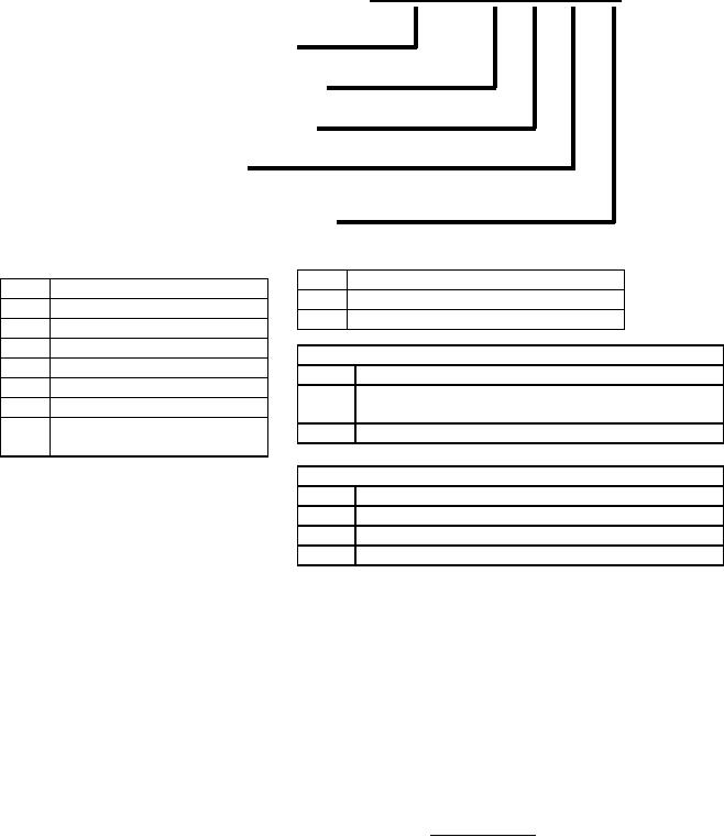
PART NUMBER DESIGNATION
M83513/10
A
01
P
P
Specification Sheet
Insert Configuration
Specification Sheet
Termination Length
See Table 1.
Shell Finish
Mounting Hardware
Termination Length (M83513/10 - /33 Only)
Insert Configuration
01
.109 In. Long
A
9 Contacts
02
.140 In. Long
B
15 Contacts
03
.172 In. Long
C
21 Contacts
D
25 Contacts
Shell Finish (Class M Connectors Only)
E
31 Contacts
C
Standard Cadmium Or Zinc Plated
F
37 Contacts
N
Electroless Nickel For Air Force Space Application
G
51 Contacts
(Not For Navy Use Or New Design)
H
100 Contacts
P
Passivated Stainless Steel
(Class M Connectors Only)
Mounting Hardware
N
No Jackpost Or Threaded Insert
P
Jackpost Attached
T
Threaded Insert
W
Jackpost And Threaded Insert
Figure 4. MIL-C-83513 PCB Part Number Breakdown
16. INSERTS. Inserts are designed so that they will not
18. INSERT CONFIGURATION. The insert
readily chip, crack, or break in normal service. They are
configuration is the manner in which contacts are placed
molded or bonded into the metal shell (Class M). Pin
within connector insert (Figure 3).
inserts provide adequate protection against a socket
contacting a pin before the mating pair of connectors has
19. CONTACTS. Contacts are of the reverse gender
been polarized. The insert is designed so that it cannot be
type. The live pin is installed in a protective insulator
removed from the shell (Class M). The contact retention
with the static socket protruding from a shrouded
system provides positive retention.
insulator. Contacts used on connector are as follows:
20. Solder Contacts. Solder contacts are non-removable
17. INTERCHANGEABILITY. All connectors having
from the insert and designed so that during soldering no
the same military part number are completely
components shall be damaged and no liquid solder can
interchangeable with respect to installation and
escape.
performance. Solder and crimp contact connectors are
inter-mateable.