
NAVAIR 01-1A-505-3
TO 1-1A-14-3
TM 1-1500-323-24-3
012 02
Page 14
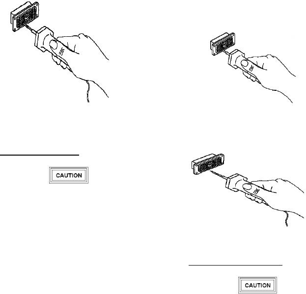
f. Remove tool and unlocked contact from
connector by withdrawing tool from connector (Figure
20).
Figure 19. Unlocking. Contact Retention
Mechanism with Unwired Contact Removal
Figure 18. Removing Contact from Connector
Tool
Mechanism
39. Unwired Contact Removal.
Caution should be exercised in the use of
tooling. Inspect tips of metal tools for
distortion of the probe before use, as damage
to the wire sealing grommet of the connector
can occur.
Figure 20. Extracting Contact from Connector
Mechanism
a.
Select correct removal tool (Figure 10).
40. Broken Wire Contact Removal.
b. With rear of connector exposed, remove
sealing plug from insert cavity of contact to be
removed.
c. Press and hold tool until tip of tool is aligned
Caution should be exercised in the use of
with contact to be removed.
tooling. Inspect tips of metal tools for
distortion of the probe before use, as damage
d. Axially align removal tool with contact to be
to the wire sealing grommet of the connector
removed.
can occur.
e. Insert removal tool tip into contact cavity to
a.
Select correct removal tool (Figure 10).
butt contact wire barrel; then slide removal tool sleeve
over contact and exert pressure until sleeve bottoms
b. Insert tip of removal tool about l/8 inch into
(Figure 19).
cavity at rear of connector.