NAVAIR 01-1A-505-3
TO 1-1A-14-3
TM 1-1500-323-24-30
13 02
1 September 2011
Page 3
13. DESIGN AND CONSTRUCTION. Connectors
9. Housing Configuration. The housing
and accessories are designed and constructed to
configuration is standard or Electro Magnetic
withstand normal handling incidental to installation
Interference (EMI).
10. Shell Size. The shell size is indicated by letter
and maintenance.
number one or two which is the shell width in inches.
14. INTERCHANGEABILITY. All connectors
11. Plug or Receptacle Designation. The plug or
having the same part number are completely
receptacle designation is indicated by a letter (P =
interchangeable with each other with respect to
Plug, R = Receptacle flangeless, F = Receptacle
installation and performance.
flanged).
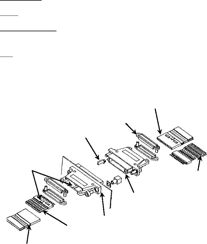
15. INSERTS. MTC inserts are available in 20-cavity
12. Plating. The connector plating is designated by a
and 5-cavity versions. The 20-cavity insert accepts
number, 2 for nickel (not for Navy or new design use),
size 20-22 crimp contacts (24 AWG to 20 AWG wire).
or 3 for Cadmium over Nickel plating.
The 5-cavity insert accepts size 1614 crimp contacts.
Insertion/extraction of the contacts is rear release. See
Figure 3.
Electrical Co nnector Ca ble/Panel
M ounting M TC-100
Removable Wafers with Fixed Contacts
To Define A Connecto r Select A Shell
And Two Wafers
Cable Clamp
User Defined Keying
Wafers Keyed To Shells
Solder pak for like AWG
Round Wire Termination
Shell Polarization
Panel Mounting Receptacle Connector
Pre-Assembled Solder Sleeves for Mixed
AWG Round Wire Termination
Booted Wafers for Flat Cable T er minatio n

