
NAVAIR 01-1A-505-3
TO 1-1A-14-3
TM 1-1500-323-24-3
014 02
1 September 2011
Page 3
1.
INTRODUCTION.
2. This Work Package (WP) covers commercial EPX
d. Both are modular with interchangeable inserts.
series A and series B connector maintenance,
EPXA acceptable for smaller wire bundles. EPXB can
procurement and tooling.
accommodate twice the contacts.
3. DESCRIPTION. This connector displays the
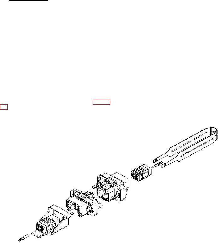
e. EPXA has two quarter-turn fasteners, 16 keying
following characteristics:
positions and a maximum contact density of 20 size 22
contacts (Figure 1).
a. All EPX connectors employ removable inserts
and replaceable Power, Signal, Coaxial, Twinax, Trariax
f.
EPXB has two Shell Sizes.:
and Quadrax contacts. They also can accommodate Fiber
Optic termini which are the same as MIL-DTL-38999,
(1) Shell Size 1 has two quarter-turn fasteners,
Series III.
16 keying positions and a maximum contact density of
48 size 22 contacts (Figure 2).
b. Both EPXA and EPXB are designed to ensure
proper orientation of the mating halves prior to closure.
(2) Shell Size 2
has one central
jackscrew/jack nut, 12 keying positions and a maximum
c. Both EPXA and EPXB can include EMI
contact density of 96 size 22 contacts (Figure 3).
shielding using appropriate backshell (refer to WP 014
Receptacle
Grounding
Shell
Device
Figure 1. EPXA Breakdown