
NAVAIR 01-1A-505-3
TO 1-1A-14-3
TM 1-1500-323-24-3
014 02
1 September 2011
Page 5
4. Wire Sealing. Wire sealing for environmental
operational characteristics. These accessories are covered
connectors is accomplished by the use of a grommet seal
in WP 014 03.
designed to seal against the inserted wire outside
9.
EPXA CONNECTORS.
diameter.
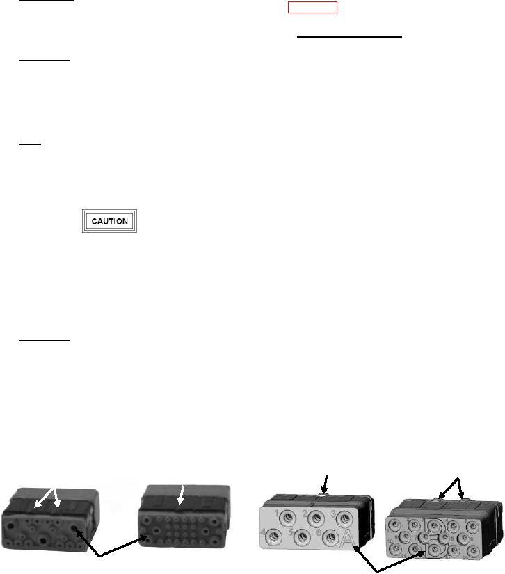
5. Mating Seal. Plugs and receptacles with pin inserts
10. EPXA connectors have smaller shells and are only
have a resilient face with individual pin barriers so as to
available in aluminum with a electrolytic nickel over
seal against the hard face socket insert. The resilient
electroless nickel finish. They are available with inserts
interface seal provides individual contact seals in the
that accommodate a maximum 20, size 22 contacts.
mated condition between each contact and the shell. (See
Figure 4).
11. PART NUMBER. EPX connectors have
interchangeable inserts the connector shell and insert
6. Shell. Shells, including mounting flanges, are of one
must be ordered separately. The part number contains the
piece construction and designed to allow various
information necessary for the proper selection and
configurations of removable inserts. The EPXA is an
procurement (Figure 5 and 6).
aluminum shell and the EPXB1 and EPXB2 and
available in aluminum and composite.
12. MILITARY SPECIFICATION. The EPX
connectors are a commercial type and therefore do not
have a military specification. Some of the contacts and
tooling are controlled under military or SAE
specifications.
The use of lead-free solder in place of tin-lead
13. DESIGN AND CONSTRUCTION. The
solder is expressly prohibited as part of any of the
connectors and accessories are designed and constructed
repair processes addressed throughout this technical
to withstand normal handling during installation and
manual. Any contamination of a lead-free assembly
maintenance.
with tin-lead solder may significantly reduce the
reliability of the assembly.
14. INSERTS. The entire insert of the EPXA assembly
is an individual part designed to provide suitable support
7. Polarization. EPXA and EPXB1 both have 16
around the wires and sealing (for class E inserts, see
keying positions and the EPXB2 has 12 keying positions.
Figure 6), and is removable/replaceable with different
Connectors can be ordered with or without keying device
configurations of inserts (Figure 6, 7 and Table 1). The
installed.
inserts align with the connector shell by a keyway.
EPXA use keyway A as shown in Figure 8.
8. CONNECTOR ACCESSORIES. Connector
accessories are added to a connector to maintain its
Keying A
Keying B
Keying A
Keying B
Interfacial Seal
Front View
Keying Letter
Rear View
Figure 4. EPX Insert Interfacial Seal and Keying