TM 1-1510-262-10
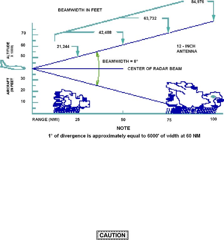
Figure 3-11. Radar Relector size versus Beam Width
(4) RANGE Control. The RANGE control is used to select the maximum display range. On the WXP-
850A/B, the RANGE control is a rotary switch. Turbulence (TURB or WX+T modes) can only be detected on the
5, 10, 25, and 50 -nmi ranges. (This is shown on the WXP-850A/B RANGE control markings.) With the EFI-890R
system, all of the selectable ranges provide one half-range arc in the center of the MFD (if weather radar is selected
on the MFD s control panel along with a selector format), with half-scale range annunciation at the right end of the
range arc. Full range annunciation may appear at the right of the dashed full-range arc on the MFD. The range and
the distance each range arc represents is annunciated in the upper right corner of the display. The ranges 5, 10,
25, and 50 nmi contain 5 range arcs; ranges 100 and 200 contain 4 arcs; and 300 range contains 3 range arcs. For
example, if a range of 50 nmi is selected, 50/10 is annunciated on the display. This represents the range selected
(50 ) and the distance between range arcs. (From the apex, arcs are at 10, 20, 30, 40, and 50 nmi). Extending
outward from the apex of the display is a blanked range area. The size of the blanked range area equals one eighth
of the selected range. The pilot should remember that the area between the apex and perimeter of the blanked
range would not display any targets.
The pilot is reminded to always keep the display blanking range in mind during and after aircraft
maneuvers in the presence of potential severe weather. If one of the longer ranges were selected
during and after aircraft maneuvers, it would be possible to allow weather targets to slip within the
blanking range and therefore not be displayed. The shortest practical range should be momentarily
selected both during and following aircraft maneuvers to ensure radar display of close-in weather
that may be within the blanking range.
(5) GCS (Ground Clutter Suppression) Pushbutton. The ground clutter suppression feature is enabled
by pressing the GCS button so that the function is on. This is a latching push-on/push-off switch on the WXP
(button in to enable). When selected, "GCS" is annunciated on the MFD. GCS is operable only in the WX and
WX+T modes. When selected, GCS reduces the intensity of ground returns so that most of them disappear from
the display, allowing better deinition of precipitation returns. Any mode or range change on the WXP automatically
3-30

