TM 1-1520-264-23
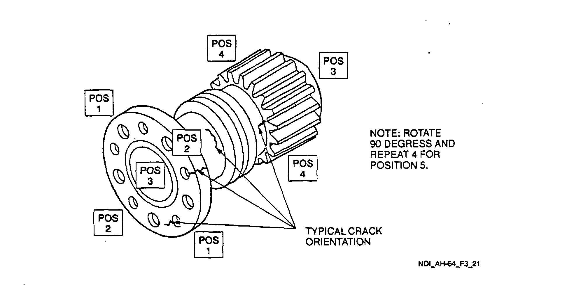
Figure 3-21. Intermediate Gearbox Flange and Shouldered Shaft
3.21.3.7
Marking and Recording of Inspection Results. Mark and record the inspection results as required by
paragraph 1.3.
3.21.3.8
Demagnetization. With the switch remaining in the AC position, place the probe/yoke legs in the same
position used for magnetizing. Press the test switch and withdraw the probe/yoke from the part for a distance of two feet
before releasing the switch.
3.21.4 Backup Method. None required.
3.21.5 System Securing. Clean the intermediate gearbox flange and shouldered shaft thoroughly to remove all residual
magnetic particle media. Refer to Post Cleaning and Restoration of Part or Area After NDI, paragraph 1.4.16. The
intermediate gearbox flange and shouldered shaft require installation in accordance with the applicable technical
manuals listed in Table 1-1.
3.22
TAIL ROTOR GEARBOX (ET).
3.22.1 Description (Figure 3-1. Index No. 22). The tail rotor gearbox transmits power from the intermediate gearbox to
the tail rotor head while changing the drive angle 900. The tail rotor gearbox is mounted on the vertical stabilizer.
3.22.2 Defects. This inspection is used to verify crack indications found visually on the tail rotor gearbox. No cracks
are allowed.
3-49