TM 1-1520-264-23
NOTE
If during setup the flying spot deflects upward or to the side when the probe passes over
the bad part, instead of the desired down deflection toward the alarm box, Press SPCL
and toggle to a different phase setting (90,180, or 270), and repeat d. and e. Continue to
try phase setting until the flying spot moves in the desired down direction.
f.
Place probe on good area of test block and press RUN. Flying spot should be near the top center of the ACTIVE
screen. If not, press NULL. Slide probe from good to void area and note response from flying spot. This response
should provide both amplitude (vertical) and phase (horizontal) movement. The default gate/alarm setting may
be incorrect for this setup. Turn off or reset gate/alarm as desired.
g.
The Bondmaster is programmed to automatically set test parameters to a start-up or initial bond test. By
following the steps outlined above, adjustments to the FREQ, GAIN, and ALARM can help to refine the
selectivity in locating defects among differing composite materials.
4.3.3.6 Inspection Procedure. Refer to Bond Test Method, paragraph 1.4.6 and inspection areas shown in Figure 4-3.
Place probe in location where test for void is desired and press NULL. Move probe from good to suspect area and note
response. A strong amplitude change and phase shift similar to the test block is indicative of a void.
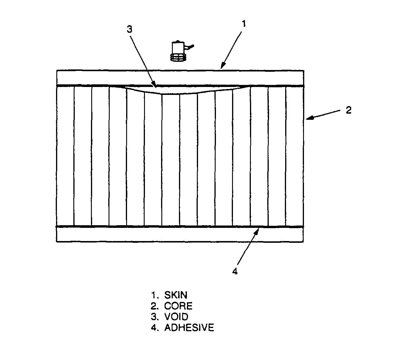
Figure 4-3. Honeycomb Core Fuselage Panels, Vertical Fin, etc.
4-9