
TM 10-4930-351-14
0003 00
The fuel transfer pump is a centrifugal pump with an impeller to move the pumpage. A positive displacement, rotary vane
pump on the same shaft serves as a priming pump for the main impeller, allowing the pump to be started with a dry system.
Fuel is drawn from the fuel drums through suction hoses into a three-way pump inlet manifold. The impeller rotation induces
a swirling motion in the fuel in the body of the manifold which, if not corrected, would cause the pump to cavitate. To correct
this situation, three equally spaced fins in the manifold outlet straighten the flow, reducing pump cavitation and increasing
efficiency. The inlet manifold empties directly into the main impeller cavity of the fuel transfer pump which discharges the
pumpage through a discharge housing to the liquid fuel filter-separator. A flapper-type check valve in the discharge housing
prevents the flow of fuel back into the fuel transfer pump, enabling the integral vane pump to move fuel.
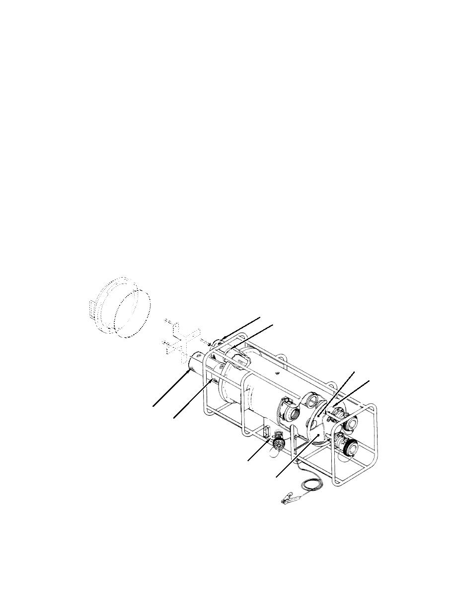
The filter-separator module, figure 3, houses a horizontal vessel containing three coalescer elements (1) to remove particles
from the pumpage and coalesce entrained water, and a separator element (2) covered by a teflon coated screen to remove the
water drops from the pumpage. The coalescer elements (1) are arranged in the lower portion of the filter vessel and the
separator element (2) is placed in the upper portion. The coalescer elements (1) are mounted to an inlet bulkhead (3) which
creates an inlet chamber in the inlet/outlet end of the filter vessel. The outlet port (4) passes completely through the chamber.
Incoming pumpage impacts a diverter plate (5) which prevents the pumpage from forcefully impacting the lower coalescer
element (1) and equalizes the pressure in the chamber. Pumpage flows from the inlet chamber to the interior of the coalescer
elements (1) and through the coalescer elements into the filter vessel. As the pumpage passes through the coalescer elements
(1), particles of matter are trapped in the element and droplets of water are coalesced (grouped and formed) into larger drops.
As the pumpage is forced up towards the separator element (2), the force of gravity causes more particles to fall down to the
sump (6). At the separator element (2), the teflon coated screen allows the fuel to pass but repels the relatively large water
drops, which fall into the sump (6). The pumpage flows from the outside to the inside of the separator element (2) and out the
filter vessel outlet port (4).
This process continues as long as the pumpage flows. Most of the particulate matter and entrained water is removed during
the first pass through the filter separator. Recirculation produces increasingly cleaner pumpage.
1
2
3
4
1
1
6
5
Figure 3. Liquid-Fuel Filter Separator
0003 00-3
