TM 10-4930-351-14
OPERATOR, UNIT, DIRECT SUPPORT AND GENERAL SUPPORT MAINTENANCE
ADVANCED AVIATION FORWARD AREA REFUELING SYSTEM MODEL M100A1
DESCRIPTION AND USE OF OPERATOR CONTROLS AND INDICATORS
1
5
2
6
2
3
4
7
2
13
8
2
11
10
12
9
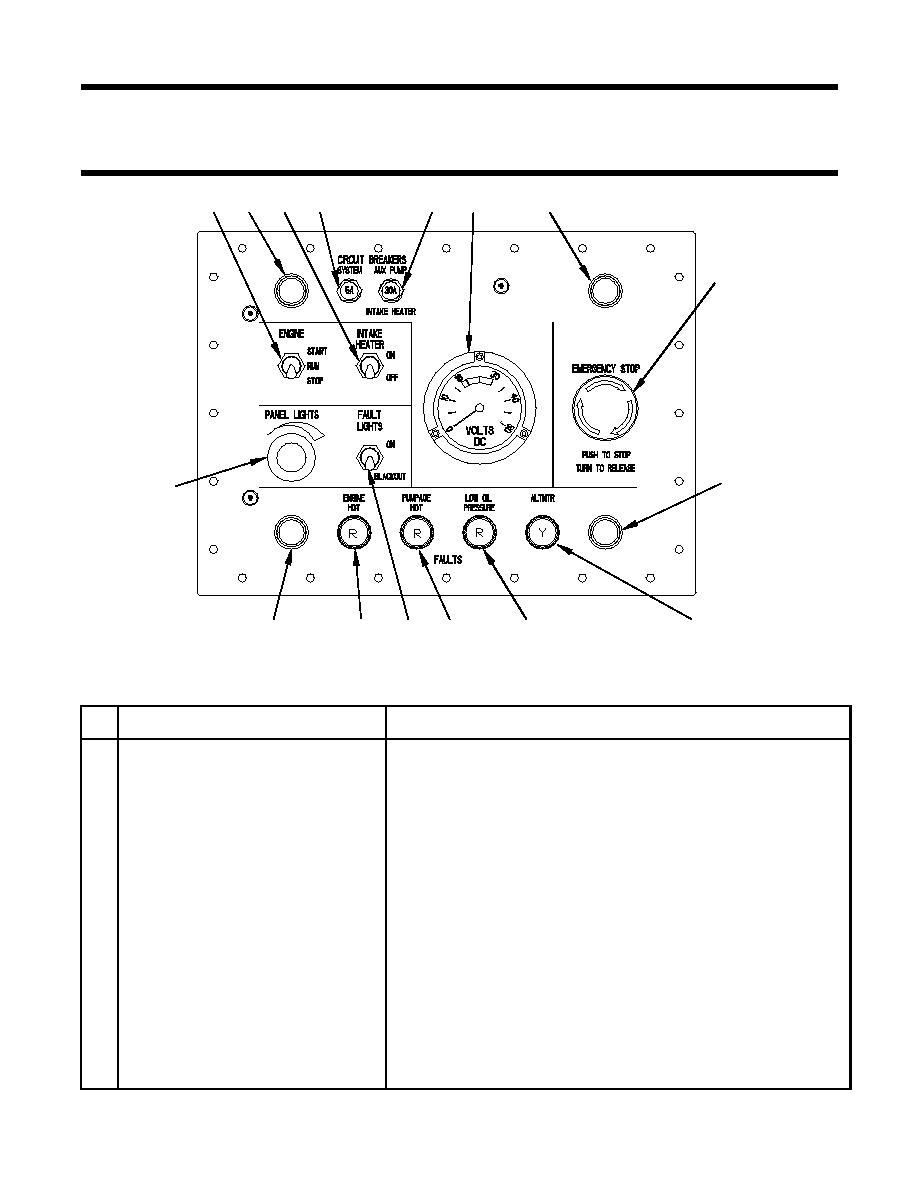
Figure 1. Control Panel
Table 1. Control Panel Controls and Indicators
No.
Name
Function
1
ENGINE START/RUN/STOP toggle
Momentary START position operates engine starter; RUN position enables
switch
system operating power; STOP position stops engine.
2
Panel Light
Hooded LED's provide illumination for control panel.
3
INTAKE HEATER ON/OFF switch
Enables power to engine intake air heater.
4
SYSTEM circuit breaker
5 amp, push-to-reset circuit breaker for system electrical power.
5
AUX PUMP/INTAKE HEATER circuit
30 amp, push-to-reset circuit breaker for auxiliary pump and engine intake
breaker
heater.
6
Provides constant readout of system voltage.
7
EMERGENCY STOP operator
Stops engine when depressed; latches in stop position, must be rotated in
direction of arrows to release. Closing control box cover latches operator in
stop position.
8
ALTNTR indicator
Illuminates YELLOW when alternator output is less than battery voltage.
9
LOW OIL PRESSURE indicator
Illuminates RED when engine oil pressure decreases below safe limits.
Illuminates RED when pumpage temperature exceeds 175 F (79 C).
10
PUMPAGE HOT indicator
11
FAULT LIGHTS ON/BLACKOUT switch Enables/disables control panel fault lights and panel lights.
Illuminates RED when engine oil temperature exceeds 275 F (135 C).
12
ENGINE HOT indicator
13
PANEL LIGHTS dimmer
Dims or brightens panel lights when rotated.
0004 00-1


