TM 55-1500-345-23
CODE
NO.
DIRECTIONS
WORDING
C-12 left side fuselage, fwd of cabin door.
Upper marking 1/2-in. aircraft black letters,
lower marking 1/2-in. black letters. See
10
Detail C. RC-12, aft of cabin door, 1/2-in.
LEVEL POINT
aircraft black letters. See Detail F. (Use
gloss black paint part number G2017 (MFG
U.S. Paint) C-12 only) (Use flat black paint part
number G2002 (MFG U.S. Paint) RC-12 only)
Left and right top of horizontal stabilizer
ACCESS ASN FLUX DETECTOR
CAUTION: USE NON-MAGNECTIC
1/2-in. and 1/4-in. aircraft black letters.
11
SCREWS IN COMPASS
Both engine nacelles, inside each
outboard main landing gear door, 1/2-in.
NORMAL PRESSURE 92-96 PSI*
12
73-77 PSI**
aircraft black letters. *C-12, **RC-12,
60-64 PSI***
*** C-12 High Flotation.
Aft, outboard sides of each engine
CAUTION: DISCONNECT ELECTRICAL WIRING
13
nacelle, above each main landing gear
AND PLUMBING BEFORE REMOVING WING
door, 1/2-in. aircraft black letters.
Left side of fuselage under cockpit
U.S. ARMY
window. Enter appropriate model" and
14
U.S.A. SERIAL NO. 00000
aircraft serial number. 1/2-in. aircraft black
letters. RC-12 only.
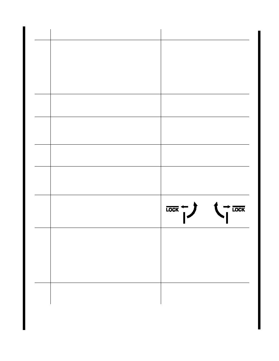
C-12, inboard and outboard fwd sides of
both engine cowlings, four places on each
15
cowling, black. C-12 and RC-12, black
vinyl decal.
C-12, aft of nose wheel well and left of
JACK PAD
fuselage centerline. Also two on bottom of
wing stubs inboard of each engine nacelle.
16
1/2-in. black letters. C-12 and RC-12,
1/2-in. aircraft black letters. (Use gloss black
paint part number G2017 (MFG U.S. Paint)
C-12 only) (Use flat black paint part number
G2002 (MFG U.S. Paint) RC-12 only)
Locate on inboard side of left nose gear
NORMAL PRESSURE 55 60 PSI
17
door, 1/2-in. aircraft black letters.
Figure 10-1. Exterior Markings, C-12 / RC-12 (Sheet 16 of 22)
Change 9
10-17


