
TM 55-1510-215-10
1.
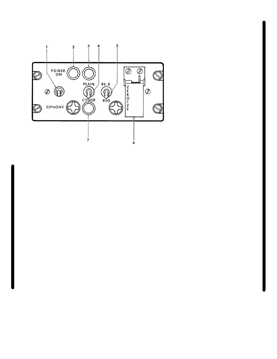
POWER ON switch
2.
POWER ON indicator
3.
PLAIN indicator
4.
PLAIN-CIPHER switch
5.
RE-X-REG switch
6.
ZEROIZE switch
7.
CIPHER indicator
AV 094958
Figure 3-3. Voice Security Control-Indicator
NOTE
2. PLAIN/CIPHER switch (CIPHONY
control-indicator) - PLAIN.
The POWER ON switch must be in
the ON position regardless of the
3. Microphone switch - Press.
mode of operation, whenever the
voice security (CIPHONY) KY-28 is
(4) Transmitter
operating
procedure
installed in the aircraft.
(CIPHER).
(2) Receiver Operating Procedure.
1. Transmitter-interphone
selector
(audio control panel) - No. 1 position.
1. SQUELCH switch (FM
COMM
control panel) -As required.
2. PLAIN/CIPHER switch (CIPHONY
control-indicator) - CIPHER.
2. Mode selector (FM COMM control
panel) - T/R or PTT.
3. RE-X REG switch (CIPHONY
control-indicator) - As required (RE-
3. Frequency selectors (FM COMM
X position only if distant station is
control panel) - As required.
using retransmitting equipment).
(3) Transmitter operating procedure (PLAIN).
4. Microphone
switch
-
Press
momentarily (interrupted tone from
1. Transmitter-indicator selector (audio
voice security unit should no longer
control panel) - No. 1 position.
be heard).
Change 5 3-5
