
TM 55-1510-215-10
(b) #1. Selects COMM 1 position.
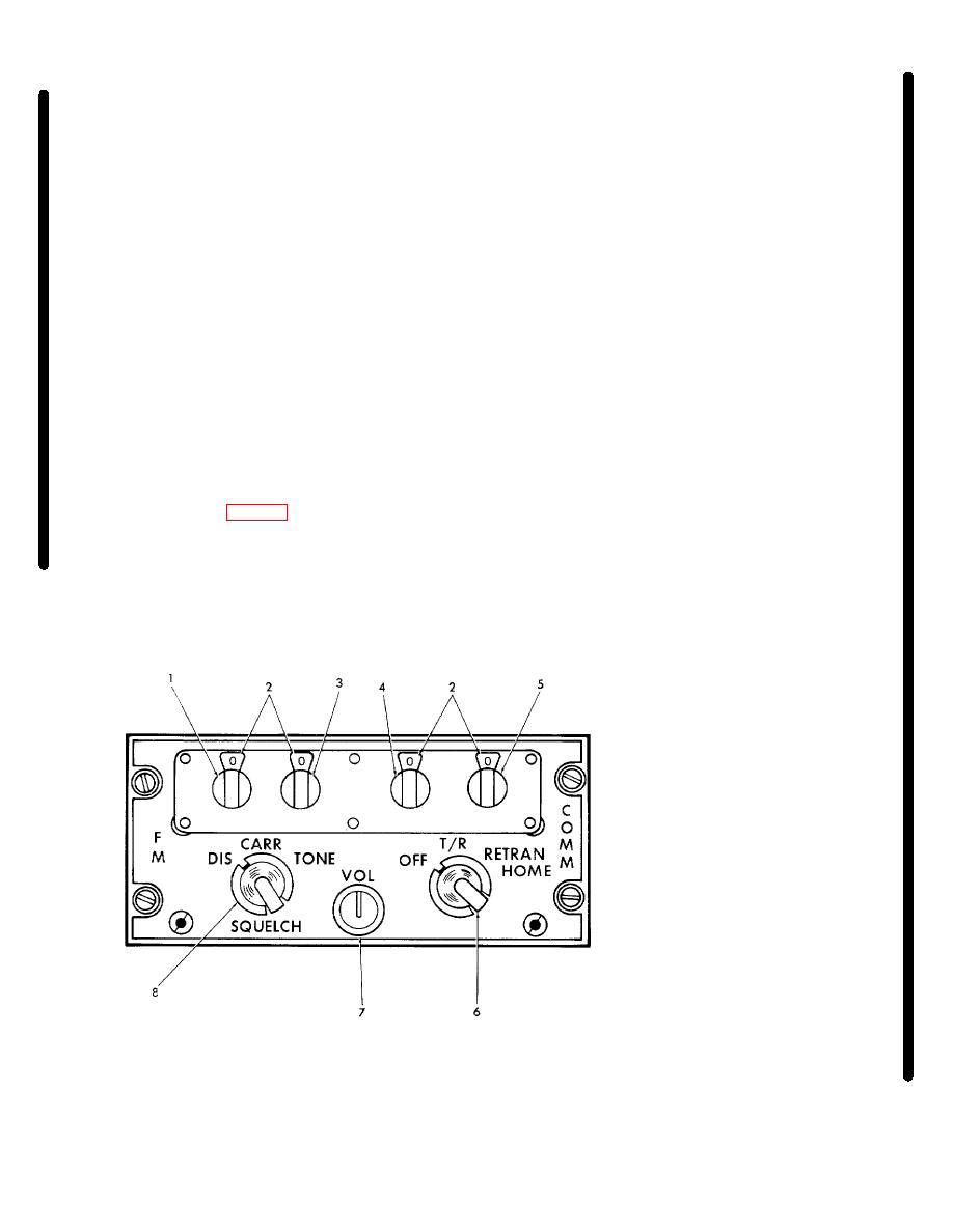
communications in the 30.00 to 75.95 MHz range for a
distance of approximately 50 miles. The FM liaison set
(c) #2. Selects COMM 2 position.
is used for voice communications and FM homing. The
(d) #3. Selects UHF position.
audio output is applied to the respective audio control
(e) #4. Selects HF radio position (if
panel where it is made available to the headsets. Power
installed).
for the FM liaison set is fed through 50-ampere
AVIONICS NO. 1 and AVIONICS NO. 2 circuit breakers,
(f) PA.
Permits the flight crew to
located on the copilot's circuit breaker panel. The unit is
address aft cabin occupants over the passenger address
speakers.
protected by a 10-ampere circuit breaker, placarded FM,
located on the copilot's subpanel.
(4) Headphone audio select buttons. Selects
audio input to heard on the headphones.
a. Controls and Functions.
(1) Megahertz selector. Tunes transceiver in
d. Operating Procedures.
10-MHz, as indicated by the first digit of the frequency
indicator.
1.
AVIONICS MASTER switch - ON.
2.
MIC SELECT switch - As required.
3.
Audio select button - As required.
(2) Frequency indicator.
Indicates frequency
to which transceiver is tuned.
4.
INT VOL - Adjust as required if INT is
selected.
(3) Megahertz selector. Tunes transceiver in
1-MHz, as indicated by the second digit of the frequency
3-7. FM Liaison Set (AN/ARC-131) (If installed).
indicator.
The FM liaison set (fig. 3-2) is a radio transceiver
(4) Kilohertz selector. Tunes transceiver in
which provides two-way frequency modulated (FM)
100-kHz, as indicated by the third frequency indicator.
1.
Megahertz (10) selector
2.
Frequency indicator
3.
Megahertz (1) selector
4.
Kilohertz (100) selector
5.
Kilohertz (10) selector
6.
Mode selector
7.
VOL control
8.
SQUELCH switch
AV 094957
Figure 3-2. FM Liaison Set (AN/ARC-131)
Change 5 3-3
