
TM 55-1510-215-10
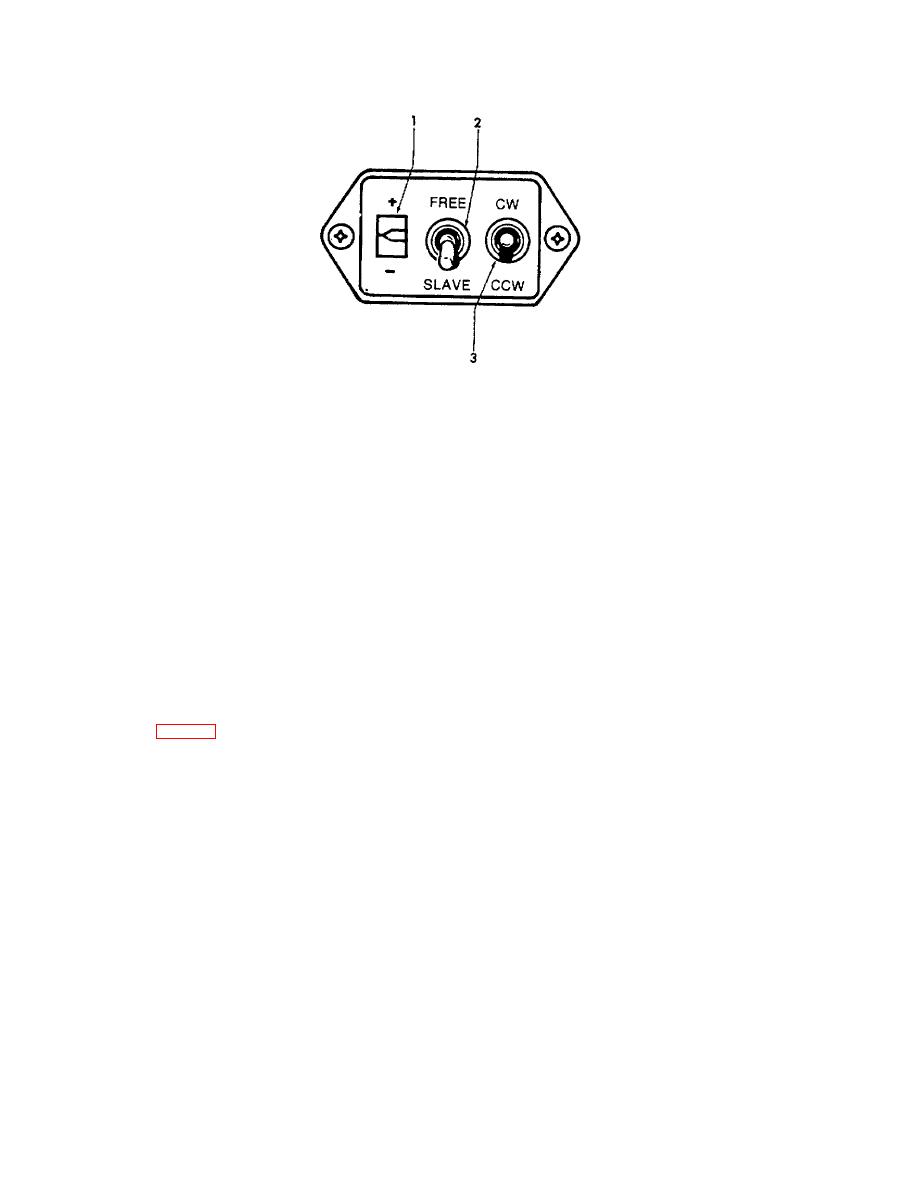
1.
Slave meter
2.
SLAVE/FREE gyro switch
3.
CCW/CW switch
Figure 3-7. Gyromagnetic Compass Slave Control
(a) Distance. Distance to VORTAC to
in SLAVE position, the system is in the slaved gryo
RNAV waypoint is displayed on the left portion of the
mode. When placed in FREE position, the system is in
display, indicated by the legend NM.
Distance is
the free gryo mode.
indicated to the nearest tenth of a nautical mile, from 0 to
99.9 nautical miles, and to the nearest nautical mile,
(3) CCW/CW switch. Placing the switch in
from 100 to 389 nautical miles.
the CCW position, when the system is in the gyro mode,
causes the compass card to rotate counterclockwise.
(b) Groundspeed.
Goundspeed is
When the switch is placed in the CW position, the
shown by the middle portion of the display, indicated by
compass card rotates in the clockwise direction.
the legend KT It is indicated to the nearest knot from 0 to
99 knots. DME ground speed is only accurate when
3-16. Pilot's Horizontal Situation Indicator.
flying a direct course to or from the VORTAC or RNAV
waypoint.
a. Description.
The pilot's horizontal situation
(c) Time-to-station.
Time-to-station
indicator (HSI) (fig. 3-8) combines numerous displays to
(TTS) is displayed by the right portion of the display,
provide a presentation of the aircraft position. The
indicated by the legend MIN. It is displayed to the
indicator displays the aircraft position relative to a VOR,
nearest minute, from 0 to 99 minutes, with 99 indicated
localizer, glide slope beam, RNAV waypoint, TACAN,
for any longer time-to-station. Time-to-station is only
and selected heading, with respect to magnetic north.
accurate for a course directly to or from a VORTAC or
The rotating heading dial is driven by the pilot's compass
RNAV waypoint.
system. Any warning flag in view indicates that portion
of the HSI display is unreliable.
In addition, the
(d) Radar altitude.
Radar altitude is
horizontal situation indicator incorporates a DME readout
shown as dashed lines on the middle display between
display. Readout brightness is automatically controlled,
2500 and 1000 feet, and numerically to the nearest 10
with respect to cockpit ambient lighting, by a photo-cell.
feet from 990 to 0 feet. The appearance of the letters AL
on the right side of the display, and the blanking of KT
b. Controls and Functions.
and MIN, indicate radar altitude information is being
displayed.
(1)
DME readout display. Provides
a digital display of DME information.
The digital display indicates the source of the frequency
information which is controlling the DME. Between the
left and middle displays, a 1 is displayed when the DME
XFER switch is set to NAV 1, likewise 2 when NAV 2 is
3-14 Change 10
