TM 55-2840-241-23
f. Installation.
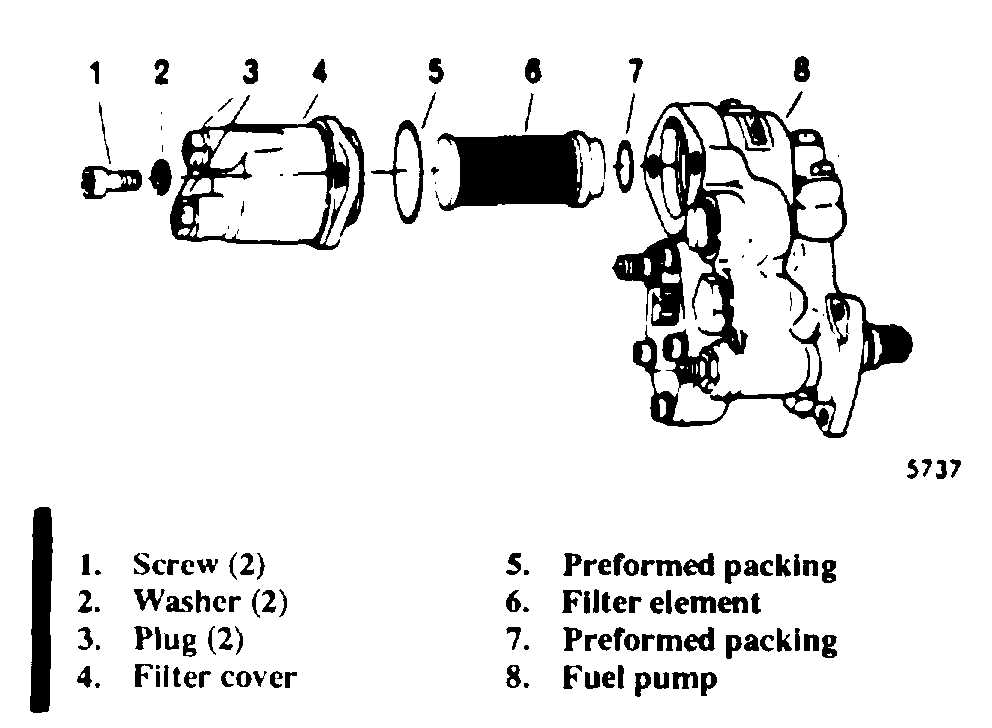
Figure 5-4. Fuel Filter Replacement
b. Disassembly. Remove lockwire and separate
filter element (68) and metallic O-ring seal (67) from
filter housing (66). When a vise is used in [he
disassembly, place the element hex (68) in the vise and
usc the wrench on the hex of housing (66).
c. Cleaning. Clean the filter assembly (68) ultra-
sonically if equipment is available. If ultrasonic
equipment is not available, clean the filter as follows:
(1) Cap the outlet fitting of the filter element
with a clean metal cap (AN 820-4 or equivalent).
(2) Wash the filter assembly with solvent and a
soft bristle brush.
(3) Dry the filter element with the metal cap
removed. Use low pressure air directed from the outside
to the inside of the element.
CAUTION
Do not use a cloth to dry the filter
element. Lint from cloth could cause
contamination.
d. Inspection. Inspect the filter assembly for dirt or
damage. Replace unserviceable filters.
e. Assembly. Apply high temperature lubricant
(item 14, table 2-2) lightly to the element (68) threads.
Assemble the metallic O-ring seal (67) and housing (66)
over the filter element. Tighten to 60-65 in. lb. and
secure with lockwire.
(1) Assemble clamp (65) on filter (69) and
secure it to the filter mounting bracket with bolt (63) and
nut (64). Tighten nut to 35-40 in lb. Check to ensure that
the arrow on the filter is pointing rearward.
(2) Attach air tubes (22, 78) on both ends of the
filter. Hold the filter while tightening the coupling nuts
to 80-120 in. lb.
5-12. Gas Producer Fuel Control.
a. Removal.
NOTE
Before replacing the fuel control to correct
an engine malfunction, ensure that the
pneumatic tubes and fittings are not leaking
and that the double check valve is function-
ing properly. A malfunction which appears to
be a fuel control malfunction may be caused
by erroneous pressures.
(1) Remove the self-locking nut and remove the
lever from the fuel control.
(2) Remove fuel tubes (3 and 4, figure 5-2)
between the fuel pump (24) and control (21). It will not
be necessary to disturb the clamping arrangement
between the tubes.
(3) Remove the fuel tube (16) between the
control and fireshield.
(4) Remove air tube (5) between the control
and governor.
(5) Remove air tube (7) between the control
and governor.
(6) Remove air tube (15) between the control
and accumulator.
(7) Remove air tube (9) between the control
and governor.
(8) Remove three self-locking nuts and washers
(42 and 43, figure 5-3) which secure the control to the
gearbox. Carefully remove the control from the
mounting studs.
b. Deleted.
5-8
Change 15


