2225A
TM 55-2840-241-23
Change 19 3-13
dry or wipe with a clean lint-free cloth. Blow out all crev-
ices with dry, filtered, low-pressure compressed air.
c.
Coat external bare metal surfaces including the
splines with corrosion preventive compound (item 12,
table 2-2).
d.
Attach a properly filled out DD Form 1577-2 (Un-
serviceable-Reparable tag). Refer to paragraph 3-9 for
additional information concerning tags.
e.
Prepare DA Form 2410 (Component Removal
and Repair/Overhaul Record) according to DA PAM
738-751 and place in a greaseproof envelope. (Refer to
paragraph 3-9.)
f.
Wrap the governor with barrier material (item 4,
table 2-2) to prevent contact with the cushioning materi-
al and to prevent the loss of the corrosion preventive
compound. Secure barrier material with pressure-sensi-
tive tape (item 5, table 2-2) .
g.
Prepare the container for use in accordance with
paragraph 3-15i.
h.
Install the governor upright in the container in
accordance with paragraph 3-15j.
i.
Stencil the container in accordance with para-
graph 3-9 and figure 3-5.
Section II. ENGINE HANDLING
3-18. Scope.
This section provides instructions for installation of
the engine in the turnover stand and dismantling of the
engine into major functional assemblies.
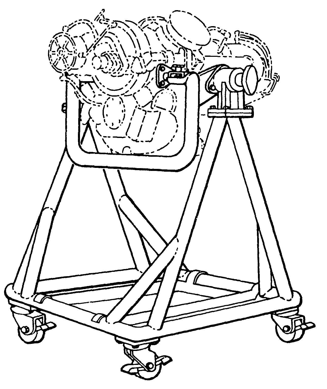
3-19. Installing Engine in Turnover Stand.
a.
Install engine assembly lift, tool No. 6796963 on
the gearbox top mounting pad and suspend the engine
from a hoist.
NOTE
Do not use the shipping container or airframe
mounting brackets in lieu of the turnover
stand mounting brackets.
b.
Install the three turnover stand, tool No. 6795579,
mounting brackets on the gearbox side and bottom
mounting pads. (See figure 3-7.)
c.
Lower the engine into the turnover stand. Ensure
that the three mounting brackets installed on the gearbox
engage the mounting bosses on the turnover stand.
d.
Slide the two clamps at the gearbox side mounts
in to engage the mounting brackets and tighten the hand
knobs.
e.
Remove the hoist and lifting tool.
Figure 3-7. Engine Assembly Turnover Stand
No. 6795579.


