TM55-2840-251-23
2-3 COMPRESSOR TURBINE ASSEMBLY (AVIM) (Continued)
2-3-3 INSTALLATION
CAUTION
When handling disk assembly take extreme care not to
damage blade tips.
1. Using an outside micrometer measure diameter of
turbine disk assembly in at least four places and determine
largest diameter. Record this diameter.
2. Turn gas generator assembly to vertical position and
install Cover (T.6) and Adapter (T.1)(13) on compressor
stub shaft. Secure with mounting bolt.
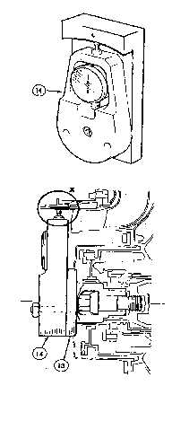
3. Set indicator of Gage (T.14)(14) to zero and install
gage on adapter (13). Secure with two nuts, torque nuts to
20 to 30 inch-pounds.
4. Measure shroud ID using gage (14). Subtract this
diameter from previously noted disk OD and divide by 2 to
give blade tip clearance which shall be 0.014 to 0.020 inch.
5. Remove gage (14).
6. If clearance is under limits, grind shroud segments
(Task 3-2-4).
7. If clearance is over limits, replace shrouds with a
suitable class (Task 3-2-5).
GO TO NEXT PAGE
2-18