TM55-2840-251-23
2-3 COMPRESSOR TURBINE ASSEMBLY (AVIM) (Continued)
2-3-1 REMOVAL
1. Before removal, measure and record compressor
turbine tip clearance, using suitable feeler gage, at center
and butt ends of each shroud segment. The average tip
clearance of the recorded readings shall be 0.011 to 0.018
inch. Clearance in excess of 0.018 inch will require
replacement of shroud (Task 3-2-5).
NOTE
The clearance at any one location must not
exceed 0.020 inch or be less than 0.009 inch.
2. If clearances are less than 0.009 inch at any location
due to high spots, the shroud segments shall be ground
over a length not exceeding one inch per segment (Task 3-
2-4).
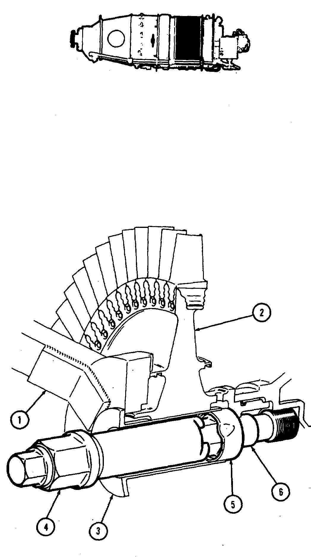
3. Install Wrench (T53)(1) at C flange of gas generator
case to prevent compressor turbine disk (2) from turning.
4. Insert Protector (T19)(3) into centerbore of disk (2).
5. Using Spreader (T.47)(4) open up keywasher (5).
Remove spreaders.
GO TO NEXT PAGE
2-14

