TM55-2840-251-23
3-2 INNER (SMALL) EXIT DUCT, SHROUD AND VANE ASSEMBLY (AVIM)
(Continued)
3-2-5 ASSEMBLE (Cont)
1. Select vanes as follows:
(Cont)
b. The average class (step
a.) shall be within 11.9 and
12.6.
c. If average is too high,
substitute a sufficient number of
vanes of a lower classification
to reduce the class average with-
in specified limits.
d. Conversely, if average
is too low, substitute a suffi-
cient number of vanes of a higher
classification to increase the
class average within specified
limits.
e. If more than one classi-
fication of vane (meaning of full
class, eg., CL11, CL12, CL13) is
required in a vane assembly, a
maximum of three consecutive full
classes may be used, provided the
spread between adjacent vanes is
not more than two classes. Vanes
of the same class should be dis-
tributed as equally as possible
around the vane assembly.
2. Install vanes as follows:
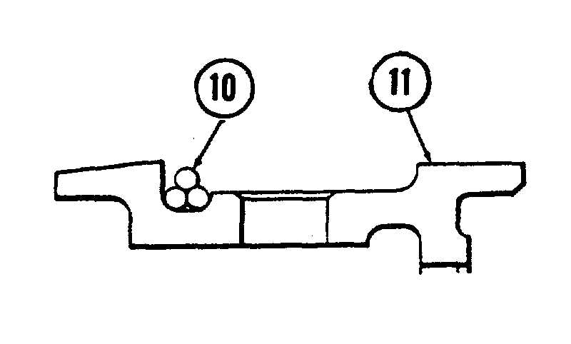
a. Cut three lengths of
ceramic fiber cord (10), each
longer than circumference of
front outer groove of compressor
turbine vane support (11). Lay
cords side-by-side so that ends
are staggered, then entwine to-
gether. Install entwined cords
in front outer groove of support
(11), insuring that there is no
gap where cord ends meet.
GO TO NEXT PAGE
3-19


